
Router Hardware Installation Guide

Opening the Chassis
iv
Cisco 1750 Router Hardware Installation Guide
78-6169-02
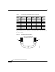
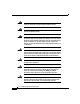
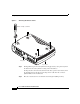
Figure 1 Removing the Chassis Screws
Step 5
Gently pull the top of the router (which is facing up toward you) up and away from
the bottom of the router (which is resting on the flat surface).
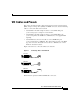
At this point, disconnect the fan, which is inside the top of the router chassis, from
the motherboard. Do this by disconnecting the fan cable from the connector
(labeled FAN) on the motherboard.
Step 6 Place the router bottom on an antistatic mat and begin installing memory.
+
5
, +1
2
, -12
V
D
C
CONSOLE
AUX
Cisco 1750
10
/10
0 E
T
H
E
R
N
E
T
SEE MANUAL BEFORE INSTALLATION
V
IC
2FX
O
P
VD
M
O
K
SLO
T 1
SLOT 2 OK
FD
X
SLO
T 0 OK
SLO
T 1 O
K
100
LINK
SLO
T 2
THIS SLOT ACCEPTS ONLY VOICE INTERFACE CARDS
SLO
T 0
1
IN USE
0
IN USE
SEE MANUAL BEFORE INSTALLATION
V
IC
2FX
S
1
IN USE
0
IN USE
Rear panel
Number 1 Phillips screwdriver
Top of router
17486