Quick Start Guide Cisco 1720 Router Cabling and Installation 1 Cisco One-Year Limited Hardware Warranty Terms 2 Overview 3 Parts List 4 Install the Router 5 Verify Your Installation 6 For More Information 7 Obtaining Documentation 8 Documentation Feedback 9 Cisco Product Security Overview 10 Obtaining Technical Assistance 11 Obtaining Additional Publications and Information
1 Cisco One-Year Limited Hardware Warranty Terms There are special terms applicable to your hardware warranty and various services that you can use during the warranty period. Your formal Warranty Statement, including the warranties and license agreements applicable to Cisco software, is available on Cisco.com. Follow these steps to access and download the Cisco Information Packet and your warranty and license agreements from Cisco.com. 1. Launch your browser, and go to this URL: http://www.cisco.
Complete the information below, and keep it for reference. Company product purchased from Company telephone number Product model number Product serial number Maintenance contract number 2 Overview This document describes the basic process of setting up and installing the Cisco 1720 router. Additional documentation can be found on Cisco.com.
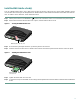
Install the Router Follow these steps to install the router. Connect the Router to the Local Network You need to provide a straight-through Ethernet cable for connecting the router to the local Ethernet network. For more information on these cables, refer to the “Cabling Specifications” chapter in the hardware installation guide that came with the router. Connect one end of the Ethernet cable to the yellow 10/100 ETHERNET port.
Install the WAN Interface Card(s) Look for a WAN interface card in one or both of the two slots on the rear of the router. If a card is already installed, connect it to the WAN line according to the Cisco WAN Interface Cards Hardware Installation Guide that came with the card. To install a card in either slot, follow these instructions: Step 1 Set the power switch to the STANDBY ( Step 2 Remove the screws that hold the slot cover in place, and then remove the slot cover.
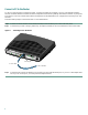
Connect a PC to the Router To use Cisco IOS software to configure the router, it must be connected to a terminal or to a PC with terminal-emulation software. Terminal emulation software should be configured with the following settings: 9600 baud, 8 data bits, no parity bits, and 1 stop bit. The Cisco 1700 Router Software Configuration Guide describes how to configure the router using Cisco IOS software.
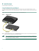
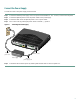
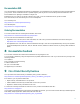
Connect the Power Supply Connect the router to the power supply as shown below. Step 1 Connect the attached power-supply cord to the power socket (labeled +5, +12, -12 VDC) on the router rear panel. Step 2 Connect the separate power cord to the power socket on the power supply. Step 3 Connect the other end of the separate power cord to a power outlet. Step 4 Turn on the router by pressing the power switch to the ON ( | ) position.
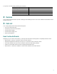
5 Verify Your Installation After the router is powered on, the following LEDs confirm that you have correctly installed your router. Table 1 LEDs LED Location What to Look For PWR Front On when power is being supplied to the router. OK Front On when the router software is loaded and functional. Blinking when the router is running a power-on self-test (POST). Continuous blinking can indicate a problem with the router.
Documentation DVD Cisco documentation and additional literature are available in a Documentation DVD package, which may have shipped with your product. The Documentation DVD is updated regularly and may be more current than printed documentation. The Documentation DVD package is available as a single unit. Registered Cisco.com users (Cisco direct customers) can order a Cisco Documentation DVD (product number DOC-DOCDVD=) from the Ordering tool or Cisco Marketplace. Cisco Ordering tool: http://www.cisco.
Reporting Security Problems in Cisco Products Cisco is committed to delivering secure products. We test our products internally before we release them, and we strive to correct all vulnerabilities quickly. If you think that you might have identified a vulnerability in a Cisco product, contact PSIRT: • Emergencies — security-alert@cisco.com • Nonemergencies — psirt@cisco.
For S1 or S2 service requests or if you do not have Internet access, contact the Cisco TAC by telephone. (S1 or S2 service requests are those in which your production network is down or severely degraded.) Cisco TAC engineers are assigned immediately to S1 and S2 service requests to help keep your business operations running smoothly.
Corporate Headquarters Cisco Systems, Inc. 170 West Tasman Drive San Jose, CA 95134-1706 USA www.cisco.com Tel: 408 526-4000 800 553-NETS (6387) Fax: 408 526-4100 European Headquarters Cisco Systems International BV Haarlerbergpark Haarlerbergweg 13-19 1101 CH Amsterdam The Netherlands www-europe.cisco.com Tel: 31 0 20 357 1000 Fax: 31 0 20 357 1100 Americas Headquarters Cisco Systems, Inc. 170 West Tasman Drive San Jose, CA 95134-1706 USA www.cisco.