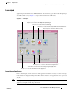
C H A P T E R 3 Getting Started This chapter describes the typical tasks you should complete to start using the Cisco 12000/10720 Router Manager application. See Figure 3-1 on page 3-2 for further details.
Chapter 3 Getting Started Cisco 12000/10720 Router Manager Workflow Figure 3-1 Workflow for Cisco 12000/10720 Router Manager Install Cisco EMF software Install C12000/10720M software Start CEMF Start a Cisco EMF session Deploy objects Enter username and password Perform Subchassis discovery Review deployment and check for alarms Module Management Fault Management Change Management Interface Management ATM Connections VLAN Sub-interface 84835 Chassis Management Layer 3 QoS Cisco 12000/10700 v3.
Chapter 3 Getting Started Starting Cisco EMF and Cisco 12000/10720 Router Manager Starting Cisco EMF and Cisco 12000/10720 Router Manager The Cisco 12000/10720 Router Manager application is viewed through the Cisco Element Management Framework (Cisco EMF). It is important to understand how Cisco EMF works before you use the Cisco 12000/10720 Router Manager application (refer to the Cisco Element Management Framework User Guide for further details).
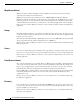
Chapter 3 Getting Started Starting Cisco EMF and Cisco 12000/10720 Router Manager The Login window (see Figure 3-2) appears. Figure 3-2 Login Window Step 2 Enter a valid user name and password. Step 3 Click Ok to proceed. When an unknown user name or password is entered, an error is displayed. Click Ok, then enter a valid user name and password. Note You have three attempts to enter a valid user name and password.
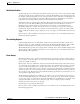
Chapter 3 Getting Started Starting Cisco EMF and Cisco 12000/10720 Router Manager Launchpad The icons displayed in the CEMF Manager and Event Manager panels on the Launchpad represent the applications provided by this Cisco EMF installation. Extra icons may appear when additional packages are installed. The icons (see Figure 3-3) represent the standard Cisco EMF tools.
Chapter 3 Getting Started Starting Cisco EMF and Cisco 12000/10720 Router Manager Map Viewer (Viewer) MapViewer allows complete flexibility in viewing, building, and monitoring your network using graphical representations of network elements. MapViewer is the primary entry point into the Cisco 12000/10720 Router Manager. When the MapViewer application is launched, a window appears corresponding to the highlighted map icon in the hierarchy pane.
Chapter 3 Getting Started Starting Cisco EMF and Cisco 12000/10720 Router Manager Notification Profiles An important aspect of a monitoring system which captures and reacts to events on the network is when and how a network operator is informed of these events. The Event Manager uses notifications for this.
Chapter 3 Getting Started Deployment PreFilter Event pre-filtering allows any event generated by the network which matches the criteria established in the filter to be “filtered out”, and thus not saved into the database. Pre-filtering offers you the capability to eliminate unwanted or undesired events from entering the management system altogether. Pre-filtering is managed through the PreFilter application or from the Event Browser.
Chapter 3 Getting Started Deployment You can also deploy either of the following logical objects: Tip • SVC—See “Deploying an SVC Object” section on page 12-22 • PVC—See “Deploying a PVC Object” section on page 12-18 • VLAN Domain, VLAN and VLAN sub-interface—See “Deploying VLAN objects” section on page 13-4 WRED (Weighted Random Early Detection) and CAR (Committed Access Rate) objects are not created using the deployment wizard.
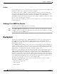
Chapter 3 Getting Started Deployment Figure 3-4 Deployment Process Workflow IP Auto-discovery of Cisco 12000/10720 series chassis Stage 1: Manually deploy a generic object Stage 2: Chassis level deployment OR Manual deployment of the Cisco 12000/10720 series chassis Stage 3: Sub-chassis level deployment Sub-chassis Discovery Manually deploy Sub-chassis objects AND/OR 84836 Optional 1. The first deployment stage is to manually deploy a Generic (Site) object.
Chapter 3 Getting Started Deployment Table 3-1 Generic Object Deployment Templates Object to be Deployed Deployment Templates Available Generic Bay IP Device Region SNMP Agent SNMP MIB-2 Agent SNMP Proxied Device Site This section provided an example that shows how to deploy a Site object. The deployment process differs slightly for other types of generic object.
Chapter 3 Getting Started Deployment Figure 3-6 Deployment Wizard - Templates Window Step 4 Select the generic object that you wish to deploy from the list supplied. In this example (shown in Figure 3-6) shows the deployment profile for a Site object is selected. The Deployment Wizard steps through a series of windows that prompt you for the information required to deploy the Site object. Step 5 Click Forward. Cisco 12000/10700 v3.1.
Chapter 3 Getting Started Deployment The Deployment Wizard - Object Parameters window appears (see Figure 3-7). Figure 3-7 Deployment Wizard - Object Parameters Window (1 of 2) Step 6 Enter the number of Sites required. A single site was entered in this example. Step 7 Click Forward. Cisco 12000/10700 v3.1.
Chapter 3 Getting Started Deployment Figure 3-8 Deployment Wizard - Object Parameters Window (2 of 2) Step 8 Enter a Site name. Each Site must have a unique name. In this example the site is called Site-srp. Step 9 Click Forward. Cisco 12000/10700 v3.1.
Chapter 3 Getting Started Deployment The Deployment Wizard - Views window appears. Figure 3-9 Step 10 Deployment Wizard—Views Window Click Select, to select a physical view. Cisco 12000/10700 v3.1.
Chapter 3 Getting Started Deployment The Object Selector Window appears. Figure 3-10 Object Selector Step 11 Select the object where you wish to place the Site object. Step 12 Click Apply. The Deployment Wizard - Views window re-appears with the selection displayed. Cisco 12000/10700 v3.1.
Chapter 3 Getting Started Deployment Figure 3-11 Deployment Wizard—Views Window Step 13 Click Forward. Note You are prompted to repeat Steps 8 to 13 if you are deploying more than one Site. The Deployment - Wizard Summary window appears. The Summary window provides details of the object you are about to deploy. Cisco 12000/10700 v3.1.
Chapter 3 Getting Started Deployment Figure 3-12 Deployment Wizard—Summary Window Step 14 Click Finish (when the Deployment Summary information is correct) to complete deployment and close the Deployment Wizard - Summary window. The new Site object (that is, Site-srp) is created and displayed in the Map Viewer window. Figure 3-13 Example Showing the Newly Deployed Site-srp Object Cisco 12000/10700 v3.1.
Chapter 3 Getting Started Deployment Note This deployment procedure can be applied to the deployment of any of the generic objects although all of the steps may not apply to the particular generic object that you are deploying. IP Auto Discovery of the Cisco Chassis Auto discovery is the application that discovers existing Cisco 12000/10720 Routers, saving time and effort. The auto discovery window can be opened from the Viewer or Discovery icon in the Launchpad.
Chapter 3 Getting Started Deployment Figure 3-14 Example of Auto Discovery Manually Deploying a Cisco 12000/10720 Chassis Tip It is recommended that you ping the Cisco 12000/10720 Router you intend to deploy to ensure the device can be contacted.
Chapter 3 Getting Started Deployment Figure 3-15 Deployment Wizard—Object Parameters (1 of 3) Step 2 Enter the number of chassis objects you want to deploy. Click Forward. Cisco 12000/10700 v3.1.
Chapter 3 Getting Started Deployment Figure 3-16 Deployment Wizard—Object Parameters Window (3 of 3) Step 3 Enter the following information: 12000 Chassis Name—Type in a name (including prefix and suffix) for the chassis you are deploying. A default prefix appears (for example, “12008”). You can delete this prefix and use your own, or you can keep it and add your own suffix. This name must be unique. IP Address—Type in the IP address for the chassis you are deploying.
Chapter 3 Getting Started Deployment Figure 3-17 Deployment Wizard—Views Step 5 Click on Select. The Object Selector window appears. Cisco 12000/10700 v3.1.
Chapter 3 Getting Started Deployment Figure 3-18 Object Selector Window Step 6 Choose the site under which you want to deploy the chassis. Click Apply. The Deployment Wizard-Views window is displayed with the selected Site object. Figure 3-19 Deployment Wizard—Views Step 7 Click Forward. A Deployment Wizard Summary window is displayed. Cisco 12000/10700 v3.1.
Chapter 3 Getting Started Deployment Figure 3-20 Deployment Wizard Summary Step 8 The Deployment Summary details appear in the Deployment Summary Screen. If the Deployment Summary information is correct, click Finish. If the Deployment Summary information is incorrect, click Cancel to stop deployment.
Chapter 3 Getting Started Deployment Commissioning and Subchassis Discovery After you deploy a chassis, the next step in creating a manageable system is to commission the chassis (which begins the process of subchassis discovery). Figure 3-21 shows a Cisco 12008 chassis map in the Physical view before subchassis discovery. Subchassis discovery discovers all physical objects (that is, modules and interfaces) within the chassis and places them onto the chassis map.
Chapter 3 Getting Started Deployment Because the chassis is the highest-level object, all objects under the chassis are commissioned as well when you commission the chassis. One level down, if you commission a GRP, you commission all physical objects underneath that level. If you commission a line card, you commission all interfaces on that line card, and so on. However, note that before you can commission any module within a chassis, the chassis object itself must be commissioned.
Chapter 3 Getting Started Deployment Figure 3-22 Chassis Configuration Window Step 2 Choose the Chassis you want to commission from the list box at left of the window. Cisco 12000/10720 Router Manager allows you to select and commission multiple chassis simultaneously. Note Step 3 Configure the parameters displayed on the Configuration and Additional Description tabs, as required.
Chapter 3 Getting Started Deployment The chassis and all objects contained within are commissioned. A status report appears in the Commission Status area displaying whether the commission action succeeded or failed. Figure 3-23 shows a Cisco 12008 chassis map in the Physical view after successful subchassis discovery. Modules and interfaces are automatically deployed within the chassis and enter the commissioned state. However, icons representing the physical objects appear in the Component Managed view.
Chapter 3 Getting Started Deployment Decommissioning a Chassis Decommissioning a chassis, decommissions all the objects within the chassis, and active management (such as polling) stops on the chassis and on all objects within the chassis. To decommission a chassis, proceed as follows: Step 1 Right click on the chassis you want to decommission, then choose Cisco 12000/10720 Manager>Configuration>Chassis>Configuration. The Chassis Configuration window appears (see Figure 3-22).
Chapter 3 Getting Started Deployment User Named vs. Auto Named Module Deployment When you deploy a module, you have two initial options: • To deploy an auto-named module • To deploy a user-named module The user-named option allows you to name the module as you like. For example, if you have a specific naming scheme you want to use, then select the user-named option. The auto-named option assigns an auto-generated name to the module, with the slot number appended to the name.
Chapter 3 Getting Started Deployment Figure 3-24 Deployment Wizard—Templates Step 2 Choose one of the Template Choices from the list displayed (either auto-named or user-named deployment). Ensure that your choice is highlighted before continuing. See “User Named vs. Auto Named Module Deployment” section on page 3-31 for further information on auto vs. user named deployment. Step 3 Click Forward. The Deployment Wizard - Object Parameters window appears. Cisco 12000/10700 v3.1.
Chapter 3 Getting Started Deployment Figure 3-25 Deployment Wizard—Object Parameters Step 4 Enter the Number of GRP objects you wish to deploy. Enter in the slot number where you want the GRP to be deployed. If you are deploying two GRPs, the primary GRP must be placed in a slot with a lower number than the secondary GRP. Caution If you deploy a module in a slot that is already occupied, deployment will fail at the Finish point.
Chapter 3 Getting Started Deployment Figure 3-26 Deployment Wizard—Views Step 6 Click Select. The Object Selector window appears. Cisco 12000/10700 v3.1.
Chapter 3 Getting Started Deployment Figure 3-27 Object Selector Window Step 7 Navigate through the hierarchy and choose the chassis that the GRP will be deployed within. Grayed out objects are not available for selection. Step 8 Click Apply. The Deployment Wizard - Views window re-appears with the location where the object will be placed. Cisco 12000/10700 v3.1.
Chapter 3 Getting Started Deployment Figure 3-28 Deployment Wizard—Views Step 9 Repeat Steps 6 to 8 to place the chassis object in each of the Physical and ComponentManaged views. Note Step 10 You are prompted to repeat steps 6 to 8 if you are deploying more than one GRP card. Click Forward. The Deployment Wizard-Summary window appears. Cisco 12000/10700 v3.1.
Chapter 3 Getting Started Deployment Figure 3-29 Deployment Wizard—Summary Step 11 The deployment summary details appear in the Deployment Summary window. If the deployment summary information is correct, click Finish. If the deployment summary information is incorrect, click Cancel to stop deployment. Note Two objects are deployed when deploying each GRP card: the GRP module object itself, and the Ethernet interface object, representing the Ethernet interface on the GRP. Cisco 12000/10700 v3.1.
Chapter 3 Getting Started Deployment Manually Deploying Line Cards The Cisco 12000 Series Router chassis supports six types of technology specific line cards (ATM, POS, Ethernet, SRP, DS-3 and Modular Ethernet). See Table 3-2 to Table 3-7 for further details. Line Cards Supported by Cisco 12000 Series Routers Table 3-2 displays a list of the ATM line cards supported by Cisco 12000 Series Routers.
Chapter 3 Getting Started Deployment Table 3-3 POS Line Cards Supported by Cisco 12000 Series Routers (continued) POS Card Type Cisco 12000/10720 Router Manager Menu Option Card Description pos-8oc3-mm POS > OC-3 8 Port > E4 MM 8 Port OC3 Multimode POS pos-8oc3-ir POS > OC-3 8 Port > E4 SM 8 Port OC3 SM Intermediate Reach POS pos-8oc3-lr POS > OC-3 8 Port > E4 SM-LR 8 port OC3 SM Long Reach POS gsr-e48-pos-8oc3-mm-sr-mtrj POS > OC-3 8 Port > E4+ MM-SR 8 Port POS OC 3 multi MOde Short Reach
Chapter 3 Getting Started Deployment Table 3-3 POS Line Cards Supported by Cisco 12000 Series Routers (continued) POS Cisco 12000/10720 Router Manager Menu Option Card Description pos-en-qoc48-sm-lr-sc POS > Enhanced OC-48 4 > E4 LR-SC 4 Port (Quad) Enhanced OC-48 Long Reach SC Connector Line Card pos-en-qoc48-sm-lr-fc POS > Enhanced OC-48 4 > E4 LR-FC 4 Port (Quad) Enhanced OC-48 Long Reach FC Connector Line Card gsr-e-qoc48-sm-sr-sc POS > Enhanced OC-48 4 > E4+ SR-SC 4 Port Enhanced OC 48 S
Chapter 3 Getting Started Deployment Table 3-3 POS Line Cards Supported by Cisco 12000 Series Routers (continued) POS Card Type Cisco 12000/10720 Router Manager Menu Option Card Description pos-16oc3-ir POS > OC-3 16 > E4 SM 16 Port OC3 SM Intermediate Reach POS pos-16oc3-mm POS > OC-3 16 > E4 MM 16 Port OC3 Multi Mode POS gsr-e48-pos-16oc3-mm-sr-mtrj POS> OC-3 16 > E4+ MM-SR 16 Port OC3 Multi Mode Short Reach POS gsr-e48-pos-16oc3-sm-ir-lc POS > ISE > OC-3 16 > IR 16 Port OC3 SM Intermedi
Chapter 3 Getting Started Deployment Table 3-5 displays a list of the DS-3 line cards supported by Cisco 12000 Series Routers. Table 3-5 DS-3 Line Cards Supported by Cisco 12000 Series Routers Card Type Cisco 12000/10720 Router Manager Menu Option Card Description copper-6ds3 DS3 > 6 Port 6 Port Copper DS3 Interface Line Card copper-12ds3 DS3 > 12 Port 12 Port Copper DS3 Interface Line Card Table 3-6 displays a list of the E3 line cards supported by Cisco 12000 Series Routers.
Chapter 3 Getting Started Deployment Line Cards Supported by Cisco 10720 Routers Table 3-8 displays a list of the SRP line cards supported by Cisco 10720 Routers.
Chapter 3 Getting Started Deployment To deploy a line card of any type, proceed as follows: Step 1 Right click on the chassis object under which you want to deploy the line card, then choose Deployment>Cisco 12000/10720 Manager>Module>ATM or POS or Ethernet or DS-3, then choose the exact type of line card to be deployed (for example, OC-3 4 Port or OC12 1 Port). Now, choose the exact variant (for example, SM, or MM) if applicable. The Deployment Wizard appears.
Chapter 3 Getting Started Deployment Figure 3-31 Deployment Wizard—Object Parameters Step 4 Enter the number of line card objects you want to deploy. Step 5 Enter the slot number where the card will be deployed. Note Step 6 Deployment will fail (at the Finish point later on) if you try to deploy a module in a slot that is already occupied. Click Forward. The Deployment Wizard - Views window appears.
Chapter 3 Getting Started Deployment Figure 3-32 Deployment Wizard—Views Step 7 Click Select to choose where you wish to place the object within the view. The Object Selector window appears. Cisco 12000/10700 v3.1.
Chapter 3 Getting Started Deployment Figure 3-33 Object Selector Window Step 8 Choose the chassis you want to place the ATM line card under. Objects which are not available for selection are greyed out. Click on the + sign to expand the view. Select the chassis under which you want to deploy the line card. Step 9 Once you have highlighted your selection, click Apply. The Deployment Wizard - Views window re-appears with the location where the object will be placed. Cisco 12000/10700 v3.1.
Chapter 3 Getting Started Deployment Figure 3-34 Deployment Wizard—Views Step 10 Repeat Steps 7 to 9 to place the object in each of the Physical and ComponentManaged views. Step 11 Click Forward. Note You are prompted to repeat steps 4 through 11 if you are deploying multiple line cards. Cisco 12000/10700 v3.1.
Chapter 3 Getting Started Deployment The Deployment Wizard—Summary window appears. Figure 3-35 Deployment Wizard—Summary Step 12 The deployment summary details appear in the Deployment Summary window. If the information is correct, click Finish. Click Cancel if the information is incorrect, and the deployment process stops. Note The number of objects deployed reflects the line card object plus the number of ports or interfaces on the line card.
Chapter 3 Getting Started Deployment Manually Deploying Supporting Modules The Cisco 12000 Series Router chassis support the following supporting modules: Note • Clock Scheduler Cards (CSCs) • Switch Fabric Cards (SFCs) • AC Power supply modules • Fan tray modules • Blower modules The AC power supply, fan tray and blower modules can only be discovered during subchassis discovery (that is, they cannot be manually deployed).
Chapter 3 Getting Started Deployment Figure 3-36 Deployment Wizard—Views Step 2 Click Select to choose where you wish to place the object within the view. Click on the + sign to expand the view if required. The Object Selector window appears. Cisco 12000/10700 v3.1.
Chapter 3 Getting Started Deployment Figure 3-37 Object Selector Window Step 3 Navigate through the hierarchy and choose where you wish to place the object within the view. Click on the + sign to expand the view if required. Step 4 Click Apply. The Deployment Wizard - Views window re-appears with the location where the object will be placed. Cisco 12000/10700 v3.1.
Chapter 3 Getting Started Deployment Figure 3-38 Deployment Wizard—Views Step 5 Click Forward. The Deployment Wizard—Summary window appears. Cisco 12000/10700 v3.1.
Chapter 3 Getting Started Deployment Figure 3-39 Deployment Wizard—Summary Step 6 The deployment summary details appear in the Deployment Summary window. If the information is correct, click Finish. If the information is incorrect, click Cancel to stop deployment. Cisco 12000/10700 v3.1.
Chapter 3 Getting Started Deployment Deploying a Switch Fabric Card To deploy a switch fabric card (SFC), proceed as follows: Step 1 Right click on the chassis you want to deploy the switch fabric card under, then choose the correct SFC card from the service menu Deployment>Cisco 12000/10720 Manager>12008>Module>SFC. The Deployment Wizard—Views window appears. Figure 3-40 Deployment Wizard—Views Step 2 Click Select to choose where you wish to place the object within the view.
Chapter 3 Getting Started Deployment Figure 3-41 Object Selector Window Step 3 Choose where you wish to place the object within the view. Click on the + sign to expand the view if required. Step 4 Click Apply. The Deployment Wizard - Views window re-appears with the location where the object will be placed. Cisco 12000/10700 v3.1.
Chapter 3 Getting Started Deployment Figure 3-42 Deployment Wizard—Views Step 5 Repeat Steps 2 to 4 to place the object in each of the Physical and ComponentManaged views. Step 6 Click Forward. The Deployment Wizard—Summary window appears. Cisco 12000/10700 v3.1.
Chapter 3 Getting Started Deployment Figure 3-43 Deployment Wizard—Summary Step 7 The deployment summary details appear in the Deployment Summary window. If the information is correct, click Finish. If the information is incorrect, click Cancel to stop deployment. Pre-deployment Cisco 12000/10720 Router Manager objects can be manually pre-deployed before the equipment arrives on-site.
Chapter 3 Getting Started Deployment Performing Pre-deployment Say that you are expecting the following hardware: • Cisco 12016 chassis and GRP(s) • ATM and POS line cards (with respective interfaces) To perform both manual pre-deployment and offline configuration, proceed as follows: Step 1 Manually deploy a site object. See “Manually Deploying a Generic Site Object” section on page 3-10 for further details. Step 2 Manually deploy the Cisco 12000 Series Router chassis under a site.
Chapter 3 Getting Started Deployment Cisco 12000/10700 v3.1.