Quick Start Guide Cisco Small Business 500 Series Wireless Access Point Versión en Español para México en el CD Version en français sur CD Versione italiana sul CD Deutsch Version auf CD
Welcome Thank you for choosing the Cisco Small Business WAP551 or WAP561 Wireless Access Point. The Cisco WAP551 is a single-radio, selectableband, 450Mbps data rate 802.11n access point, and the Cisco WAP561 is a dual-radio variant of the Cisco WAP551. This guide is designed to familiarize you with the general layout of the access point, describe how to deploy the device in your network, and describe how to configure the device.
2 Cisco WAP551 and WAP561 Wireless-N Access Point Features Front Panel The front panel of the devices consists of three lights: Power, WLAN, and LAN. For full descriptions of the colors of the lights and their indications, see “Verifying the Hardware Installation”. A Kensington lock slot is found under the lights. Back Panel The back panel of the devices has an RJ-45 Ethernet Port. Use the Ethernet port to power your device using PoE. It is an auto-sensing, Gigabit Ethernet (802.
3 Mounting the Cisco WAP551 and WAP561 Wireless-N Access Points You can place your access point on a desktop, or mount it on a wall or ceiling. Placement Tips • Ambient Temperature—To prevent the access point from overheating, do not operate it in an area that exceeds an ambient temperature of 104°F (40°C). • Air Flow—Both side panels have vents which must be unobstructed to prevent overheating.
To mount the WAP device to a wall or ceiling: STEP 1 Determine where you want to mount the device. Verify that the surface is smooth, flat, dry, and sturdy. STEP 2 Drill two pilot holes into the surface 2.75 inches (70 mm) apart for your Cisco WAP device. STEP 3 Insert a screw into each hole, leaving a gap between the surface and the base of the screw head.
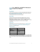
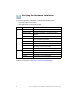
5 Verifying the Hardware Installation To verify the hardware installation, complete the following tasks: • Check the cable connections. • Check the state of the indicator lights. Label Power WLAN Activity Off Solid Green Flashing Green Solid Red Off Solid Green Solid Amber Solid Blue LAN Flashing Off Solid Green Solid Amber Flashing Description The device has no power. The device is powered on. Normal operation. Upgrading firmware or acquiring an IPv4 address. Booting or firmware upgrade failed.
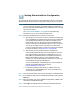
Getting Started with the Configuration 6 To configure the wireless access points, follow these steps to access the Wizard and then the web-based configuration utility from your computer. STEP 1 Connect the wireless access point to the same network (IP subnet) as your computer. The factory default IP address configuration of the access points is DHCP. Make sure your DHCP server is running and can be reached.
STEP 7 Follow the Setup Wizard instructions to finish the WAP device installation. We strongly recommend you use the Setup Wizard for the first installation.The Setup Wizard turns on the Wi-Fi radio, allowing you to connect wirelessly. For more advanced configurations, see the Administration Guide. A link to the Administration Guide is found in “Where to Go From Here” on page 11. Congratulations, you can now start using your wireless access point.
If it fails, you should get a reply similar to the following: Pinging 192.0.2.10 with 32 bytes of data: Request timed out. Possible Cause of Failure Devices Can’t Connect using Wi-Fi • Complete the Setup Wizard. The Wi-Fi radio on the device is turned off by default, and the Setup Wizard activates it. For users who do not wish to use the Setup Wizard, log into the device using a Category 5e Ethernet cable, and activate the Wi-Fi radio manually.
Because the factory default IP address configuration is DHCP, make sure that your DHCP server is running and can be reached. You may need to disconnect and reconnect the devices for them to discover their new IP addresses from the DHCP server. You can then query the DHCP server for the new IP address. See Step 2 of “Getting Started with the Configuration” on page 7 for more information on how to find the DHCP address.
9 Where to Go From Here Support Cisco Small Business Support Community www.cisco.com/go/smallbizsupport Cisco Small Business Support and Resources www.cisco.com/go/smallbizhelp Phone Support Contacts www.cisco.com/en/US/support/ tsd_cisco_small_business _support_center_contacts.html Cisco Small Business Firmware Downloads www.cisco.com/go/smallbizfirmware Select a link to download firmware for Cisco Small Business Products. No login is required.
Americas Headquarters Cisco Systems, Inc. 170 West Tasman Drive San Jose, CA 95134-1706 USA www.cisco.com Small Business Support, Global: www.cisco.com/go/sbsc 78-20584-02 Cisco and the Cisco logo are trademarks or registered trademarks of Cisco and/or its affiliates in the U.S. and other countries. To view a list of Cisco trademarks, go to this URL: www.cisco.com/go/trademarks. Third-party trademarks mentioned are the property of their respective owners.