Managing Network Adapters This chapter includes the following sections: • Overview of the Cisco UCS C-Series Network Adapters, page 1 • Viewing Network Adapter Properties, page 2 • Configuring Adapter Properties, page 5 • Managing vHBAs, page 7 • Managing vNICs, page 20 • Managing VM FEX, page 31 • Backing Up and Restoring the Adapter Configuration, page 35 • Managing Adapter Firmware, page 37 • Resetting the Adapter, page 39 Overview of the Cisco UCS C-Series Network Adapters Note The procedures in this
Managing Network Adapters Viewing Network Adapter Properties Cisco UCS P81E Virtual Interface Card The Cisco UCS P81E Virtual Interface Card is optimized for virtualized environments, for organizations that seek increased mobility in their physical environments, and for data centers that want reduced costs through NIC, HBA, cabling, and switch reduction and reduced management overhead.
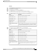
Managing Network Adapters Viewing Network Adapter Properties Procedure Step 1 In the Navigation pane, click the Server tab. Step 2 Step 3 On the Server tab, click Inventory. In the Inventory pane, click the Network Adapters tab. Step 4 In the Adapter Cards area, click an adapter in the table to display its properties. The resources of the selected adapter appear in the tabbed menu below the Adapter Cards area.
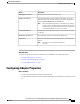
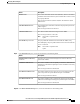
Managing Network Adapters Viewing Network Adapter Properties Name Description Configuration Pending field If this field displays yes, the adapter configuration has changed in CIMC but these changes have not been communicated to the host operating system. To activate the changes, an administrator must reboot the adapter. Description field The user-defined description for the adapter, if any. FIP Mode field Whether FCoE Initialization Protocol (FIP) mode is enabled.
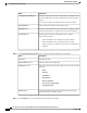
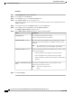
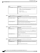
Managing Network Adapters Configuring Adapter Properties Name Description Running Version field The firmware version that is currently active. Backup Version field The alternate firmware version installed on the adapter, if any. The backup version is not currently running. To activate it, administrators can click Activate Firmware in the Actions area. Note When you install new firmware on the adapter, any existing backup version is deleted and the new firmware becomes the backup version.
Managing Network Adapters Configuring Adapter Properties Procedure Step 1 In the Navigation pane, click the Server tab. Step 2 Step 3 On the Server tab, click Inventory. In the Inventory pane, click the Network Adapters tab. Step 4 In the Adapter Cards area, select the adapter card. If the server is powered on, the resources of the selected adapter card appear in the tabbed menu below the Adapter Cards area. Step 5 Step 6 In the tabbed menu below the Adapter Cards area, click the General tab.
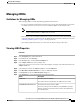
Managing Network Adapters Managing vHBAs Managing vHBAs Guidelines for Managing vHBAs When managing vHBAs, consider the following guidelines and restrictions: • The Cisco UCS P81E Virtual Interface Card and Cisco UCS VIC1225 Virtual Interface Card provide two vHBAs (fc0 and fc1). You can create up to 16 additional vHBAs on these adapter cards. Note If Network Interface Virtualization (NIV) mode is enabled for the adapter, you must assign a channel number to a vHBA when you create it.
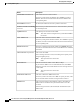
Managing Network Adapters Viewing vHBA Properties Name Description World Wide Port Name field The WWPN associated with the vHBA. To let the system generate the WWPN, select AUTO. To specify a WWPN, click the second radio button and enter the WWPN in the corresponding field. FC SAN Boot check box If checked, the vHBA can be used to perform a SAN boot. Enable Persistent LUN Binding If checked, any LUN ID associations are retained in memory until they check box are manually cleared.
Managing Network Adapters Viewing vHBA Properties Name Description RATOV field The resource allocation timeout value (RATOV), which is the number of milliseconds to wait before the system assumes that a resource cannot be properly allocated. Enter an integer between 5,000 and 100,000. The default is 10,000 milliseconds. Max Data Field Size field The maximum size of the Fibre Channel frame payload bytes that the vHBA supports. Enter an integer between 256 and 2112.
Managing Network Adapters Viewing vHBA Properties Name Description Interrupt Mode drop-down list The preferred driver interrupt mode. This can be one of the following: • MSIx—Message Signaled Interrupts (MSI) with the optional extension. This is the recommended option. • MSI—MSI only. • INTx—PCI INTx interrupts.
Managing Network Adapters Modifying vHBA Properties Name Description PLOGI Timeout field The number of milliseconds that the system waits before it tries to log in again. Enter an integer between 1,000 and 255,000. Step 14 In the SCSI I/O area, review the information in the following fields: Name Description CDB Transmit Queue Count field The number of SCSI I/O queue resources the system should allocate. Enter an integer between 1 and 8.
Managing Network Adapters Modifying vHBA Properties Step 5 Step 6 Step 7 In the tabbed menu below the Adapter Cards area, click the vHBAs tab. In the Host Fibre Channel Interfaces area, select a vHBA from the table. Click Properties to open the vHBA Properties dialog box. Step 8 In the General area, update the following fields: Name Description Name field The name of the virtual HBA. This name cannot be changed after the vHBA has been created.
Managing Network Adapters Modifying vHBA Properties Name Description Rate Limit field The data rate limit for traffic on this vHBA, in Mbps. If you want this vHBA to have an unlimited data rate, select OFF. Otherwise, click the second radio button and enter an integer between 1 and 10,000. Note PCIe Device Order field This option cannot be used in NIV mode. The order in which this vHBA will be used. To let the system set the order, select ANY.
Managing Network Adapters Modifying vHBA Properties Name Description Link Down Timeout field The number of milliseconds the uplink port should be offline before it informs the system that the uplink port is down and fabric connectivity has been lost. Enter an integer between 0 and 240,000. Port Down I/O Retries field The number of times an I/O request to a port is returned because the port is busy before the system decides the port is unavailable. Enter an integer between 0 and 255.
Managing Network Adapters Modifying vHBA Properties Name Description FLOGI Retries field The number of times that the system tries to log in to the fabric after the first failure. To specify an unlimited number of retries, select the INFINITE radio button. Otherwise select the second radio button and enter an integer into the corresponding field. FLOGI Timeout field The number of milliseconds that the system waits before it tries to log in again. Enter an integer between 1,000 and 255,000.
Managing Network Adapters Creating a vHBA Step 16 Click Save Changes. Creating a vHBA The adapter provides two permanent vHBAs. If NIV mode is enabled, you can create up to 16 additional vHBAs. Procedure Step 1 In the Navigation pane, click the Server tab. Step 2 Step 3 On the Server tab, click Inventory. Step 4 In the Adapter Cards area, select the adapter card. If the server is powered on, the resources of the selected adapter card appear in the tabbed menu below the Adapter Cards area.
Managing Network Adapters Deleting a vHBA Deleting a vHBA Procedure Step 1 In the Navigation pane, click the Server tab. Step 2 Step 3 On the Server tab, click Inventory. In the Inventory pane, click the Network Adapters tab. Step 4 In the Adapter Cards area, select the adapter card. If the server is powered on, the resources of the selected adapter card appear in the tabbed menu below the Adapter Cards area. Step 5 In the tabbed menu below the Adapter Cards area, click the vHBAs tab.
Managing Network Adapters Deleting a Boot Table Entry Name Description Target WWPN field The World Wide Port Name (WWPN) that corresponds to the location of the boot image. Enter the WWPN in the format hh:hh:hh:hh:hh:hh:hh:hh. LUN ID field The LUN ID that corresponds to the location of the boot image. Enter an ID between 0 and 255. Add Boot Entry button Adds the specified location to the boot table. Reset Values button Clears the values currently entered in the fields.
Managing Network Adapters Viewing Persistent Bindings Viewing Persistent Bindings Procedure Step 1 In the Navigation pane, click the Server tab. Step 2 Step 3 On the Server tab, click Inventory. In the Inventory pane, click the Network Adapters tab. Step 4 In the Adapter Cards area, select the adapter card. If the server is powered on, the resources of the selected adapter card appear in the tabbed menu below the Adapter Cards area.
Managing Network Adapters Rebuilding Persistent Bindings Rebuilding Persistent Bindings Procedure Step 1 In the Navigation pane, click the Server tab. Step 2 Step 3 On the Server tab, click Inventory. In the Inventory pane, click the Network Adapters tab. Step 4 In the Adapter Cards area, select the adapter card. If the server is powered on, the resources of the selected adapter card appear in the tabbed menu below the Adapter Cards area.
Managing Network Adapters Viewing vNIC Properties Viewing vNIC Properties Procedure Step 1 In the Navigation pane, click the Server tab. Step 2 Step 3 On the Server tab, click Inventory. In the Inventory pane, click the Network Adapters tab. Step 4 In the Adapter Cards area, select the adapter card. If the server is powered on, the resources of the selected adapter card appear in the tabbed menu below the Adapter Cards area.
Managing Network Adapters Viewing vNIC Properties Name Description Default VLAN field If there is no default VLAN for this vNIC, click NONE. Otherwise, click the second radio button and enter a VLAN ID between 1 and 4094 in the field. Note VLAN Mode drop-down list If you want to use VLAN trunking, select TRUNK. Otherwise, select ACCESS. Note Rate Limit field This option cannot be used in NIV mode. This option cannot be used in NIV mode.
Managing Network Adapters Viewing vNIC Properties Name Description Interrupt Count field The number of interrupt resources to allocate. In general, this value should be equal to the number of completion queue resources. Enter an integer between 1 and 514. Coalescing Time field The time to wait between interrupts or the idle period that must be encountered before an interrupt is sent. Enter an integer between 1 and 65535. To turn off interrupt coalescing, enter 0 (zero) in this field.
Managing Network Adapters Viewing vNIC Properties Name Description Transmit Queue Ring Size field The number of descriptors in each transmit queue. Enter an integer between 64 and 4096. Step 12 In the Completion Queue area, review the information in the following fields: Name Description Completion Queue Count field The number of completion queue resources to allocate.
Managing Network Adapters Modifying vNIC Properties Name Description Enable TCP Receive Side Scaling Receive Side Scaling (RSS) distributes network receive processing check box across multiple CPUs in multiprocessor systems. If checked, network receive processing is shared across processors whenever possible. If cleared, network receive processing is always handled by a single processor even if additional processors are available. Enable IPv4 RSS check box If checked, RSS is enabled on IPv4 networks.
Managing Network Adapters Modifying vNIC Properties Name Description Name field The name for the virtual NIC. This name cannot be changed after the vNIC has been created. MTU field The maximum transmission unit, or packet size, that this vNIC accepts. Enter an integer between 1500 and 9000. Uplink Port drop-down list The uplink port associated with this vNIC. All traffic for this vNIC goes through this uplink port. MAC Address field The MAC address associated with the vNIC.
Managing Network Adapters Modifying vNIC Properties Name Description Channel Number field Select the channel number that will be assigned to this vNIC. Note Port Profile drop-down list NIV mode is required for this option. Select the port profile that should be associated with the vNIC. This field displays the port profiles defined on the switch to which this server is connected. Note NIV mode is required for this option.
Managing Network Adapters Modifying vNIC Properties Name Description Interrupt Mode drop-down list The preferred driver interrupt mode. This can be one of the following: • MSI-X—Message Signaled Interrupts (MSI) with the optional extension. This is the recommended option. • MSI—MSI only. • INTx—PCI INTx interrupts. Step 10 In the Ethernet Receive Queue area, update the following fields: Name Description Receive Queue Count field The number of receive queue resources to allocate.
Managing Network Adapters Modifying vNIC Properties Name Description Enable TCP Segmentation Offload check box If checked, the CPU sends large TCP packets to the hardware to be segmented. This option may reduce CPU overhead and increase throughput rate. If cleared, the CPU segments large packets. Note This option is also known as Large Send Offload (LSO). Enable TCP Rx Offload If checked, the CPU sends all packet checksums to the hardware for Checksum Validation check box validation.
Managing Network Adapters Creating a vNIC Step 15 Click Save Changes. Creating a vNIC The adapter provides two permanent vNICs. You can create up to 16 additional vNICs. Procedure Step 1 In the Navigation pane, click the Server tab. Step 2 Step 3 On the Server tab, click Inventory. In the Inventory pane, click the Network Adapters tab. Step 4 In the Adapter Cards area, select the adapter card.
Managing Network Adapters Deleting a vNIC Deleting a vNIC Procedure Step 1 In the Navigation pane, click the Server tab. Step 2 Step 3 On the Server tab, click Inventory. In the Inventory pane, click the Network Adapters tab. Step 4 In the Adapter Cards area, select the adapter card. If the server is powered on, the resources of the selected adapter card appear in the tabbed menu below the Adapter Cards area. Step 5 In the tabbed menu below the Adapter Cards area, click the vNICs tab.
Managing Network Adapters Viewing Virtual FEX Properties If the server is powered on, the resources of the selected adapter card appear in the tabbed menu below the Adapter Cards area. Step 5 In the tabbed menu below the Adapter Cards area, click the VM FEXs tab. Step 6 In the Virtual FEXs area, review the following information: Name Description Properties button Opens a dialog box that allows you to view the properties for the selected VM FEX. Name column The name of the VM FEX.
Managing Network Adapters Viewing Virtual FEX Properties Step 10 In the Ethernet Interrupt area, review the information in the following fields: Name Description Interrupt Count field The number of interrupt resources allocated to this VM FEX. Coalescing Time field The time CIMC waits between interrupts or the idle period that must be encountered before an interrupt is sent.
Managing Network Adapters Viewing Virtual FEX Properties Name Description Completion Queue Ring Size field The number of descriptors in each completion queue. Step 14 In the TCP Offload area, review the information in the following fields: Name Description Enable TCP Segmentation Offload field If enabled, the CPU sends large TCP packets to the hardware to be segmented. If disabled, the CPU segments large packets. Note This option is also known as Large Send Offload (LSO).
Managing Network Adapters Backing Up and Restoring the Adapter Configuration Backing Up and Restoring the Adapter Configuration Exporting the Adapter Configuration The adapter configuration can be exported as an XML file to a TFTP server. Before You Begin Obtain the TFTP server IP address. Procedure Step 1 In the Navigation pane, click the Server tab. Step 2 Step 3 On the Server tab, click Inventory. In the Inventory pane, click the Network Adapters tab.
Managing Network Adapters Importing the Adapter Configuration Importing the Adapter Configuration Procedure Step 1 In the Navigation pane, click the Server tab. Step 2 Step 3 On the Server tab, click Inventory. In the Inventory pane, click the Network Adapters tab. Step 4 In the Adapter Cards area, select the adapter card. If the server is powered on, the resources of the selected adapter card appear in the tabbed menu below the Adapter Cards area.
Managing Network Adapters Managing Adapter Firmware Step 5 Step 6 In the tabbed menu below the Adapter Cards area, click the General tab. In the Actions area of the General tab, click Reset To Defaults and click OK to confirm.
Managing Network Adapters Installing Adapter Firmware From a TFTP Server Installing Adapter Firmware From a TFTP Server Procedure Step 1 In the Navigation pane, click the Server tab. Step 2 Step 3 On the Server tab, click Inventory. In the Inventory pane, click the Network Adapters tab. Step 4 In the Adapter Cards area, select the adapter card. If the server is powered on, the resources of the selected adapter card appear in the tabbed menu below the Adapter Cards area.
Managing Network Adapters Activating Adapter Firmware Activating Adapter Firmware Procedure Step 1 In the Navigation pane, click the Server tab. Step 2 Step 3 On the Server tab, click Inventory. In the Inventory pane, click the Network Adapters tab. Step 4 In the Adapter Cards area, select the adapter card. If the server is powered on, the resources of the selected adapter card appear in the tabbed menu below the Adapter Cards area.
Managing Network Adapters Resetting the Adapter Cisco UCS C-Series Servers Integrated Management Controller GUI Configuration Guide, Release 1.