
user manual
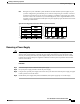
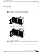

Both grids in a power redundant system should have the same number of power supplies. If your
system is configured for grid redundancy, slots 1 and 2 are assigned to grid 1 and slots 3 and 4 are
assigned to grid 2. If there are only two power supplies in a redundant- mode chassis, they should
be in slots 1 and 3. This would be a very unusual configuration, with a single B200 blade server in
the chassis. A larger configuration would require two power supplies per grid. Slot and cord connection
numbering is shown below.
Note
Figure 37: Power Supply Bay and Connector Numbering (AC Version Shown)
PS 1
PS 2
PS 3
PS 4
Server Slot 1
Server Slot 2
Server Slot 3
Server Slot 5
Server Slot 7
Server Slot 4
Server Slot 6
Server Slot 8
Front
Fan 1
Fan 2
I/O Module Slot 1
I/O Module Slot 2
Connector
PS 4
Connector
PS 3
Connector
PS 2
Connector
PS 1
Fan 6
Fan 5
Fan 4
Fan 3
Fan 8
Fan 7
Rear
279770
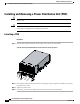
Removing a Power Supply
If you are using the Cisco UCS 5108 server chassis with one power supply (this is only supported in earlier
versions of the system software), removing the power supply will cause the servers and chassis to shut
down. If you are using more than two power supplies, and you remove one of them, the servers continue
to operate as long as the other power supplies are sufficient to meet the power requirements of the number
of servers in the chassis.
Caution
Procedure
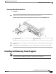
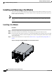
Step 1
Loosen the captive screw on the front of the power supply.
Step 2
Lift up the power supply’s handle to unseat the power supply.
Step 3
Using the lever, pull the power supply from its slot. Place your other hand under the power supply to support
it while you slide it out of the chassis.
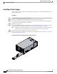
Step 4
Install a blank power supply filler panel (N20-CBLKP) if the power supply bay is to remain empty.
Cisco UCS 5108 Server Chassis Installation Guide
OL-20035-05 61
Installing and Removing Components
Removing a Power Supply