
user manual
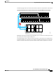

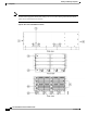
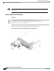

The following figure shows an invalid connection from a FEX to two separate fabric interconnects.
Figure 28: Invalid Connection for the Server Chassis and two Cisco UCS 6120XP Fabric Interconnects
I/O Module Slot 1 I/O Module Slot 2I/O Module Slot 1 I/O Module Slot 2
Chassis 1 rear
Port 1
Port 2
Port 3
Port 4
Port 1
Port 2
Port 3
Port 4
1 3 5 7 9 11 13 15 17 19 21 23 25 27 29 31
26 28 30 3218 20 22 2410 12 14 162 4 6 8
1 3 5 7 9 11 13 15
10 12 14 162 4 6 8
1 3 5 7 9 11 13 15 17 19 21 23 25 27 29 31
26 28 30 3218 20 22 2410 12 14 162 4 6 8
1 3 5 7 9 11 13 15
10 12 14 162 4 6 8
Fabric Interconnect A Rear
Fabric Interconnect B Rear
192748
◦
Both fabric interconnects should be wired identically: if port 1 on FEX 1 for a chassis goes to FI-A
port 5, then port 1 on FEX 2 goes to FI-B port 5.
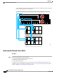
The following figure shows valid connections from FEXes in two chassis to two separate fabric
interconnects. When you connect the server chassis to the fabric interconnect do not connect the
FEXes to the fabric interconnect's expansion modules. While similar in appearance to the other
Cisco UCS 5108 Server Chassis Installation Guide
OL-20035-05 49
Installation
Proper FEX and Fabric Interconnect Port Connectivity