
user manual
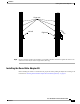
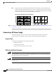
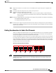

Both grids in a power redundant system should have the same number of power supplies. If your
system is configured for grid redundancy, slots 1 and 2 are assigned to grid 1 and slots 3 and 4 are
assigned to grid 2. If only two power supplies (PS) are in a redundant- mode chassis, they should be
in slots 1 and 3. Slot and cord connection numbering is shown below.
Figure 25: Power Supply Bay and Connector Numbering
PS 1
PS 2
PS 3
PS 4
Server Slot 1
Server Slot 2
Server Slot 3
Server Slot 5
Server Slot 7
Server Slot 4
Server Slot 6
Server Slot 8
Front
Fan 1
Fan 2
I/O Module Slot 1
I/O Module Slot 2
Connector
PS 4
Connector
PS 3
Connector
PS 2
Connector
PS 1
Fan 6
Fan 5
Fan 4
Fan 3
Fan 8
Fan 7
Rear
279770
Note
Step 6
Connect the server chassis to the fabric interconnect as described in Proper FEX and Fabric Interconnect Port
Connectivity, on page 48.
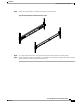
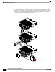
Connecting a DC Power Supply
This section describes how to connect power to the rear PDU terminals on the DC version chassis
(UCSB-5108-DC) corresponding to a UCS 5108 DC power supply (UCSB-PSU-2500DC48).
Required Tools
You must have the following tools to perform this procedure:
•
A Phillips screwdriver
•
A 10-mm wrench or socket
•
Connectors and wire for the DC circuit or circuits
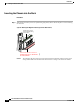
DC Power Installation Procedure
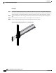
When stranded wiring is required, use approved wiring terminations, such as closed-loop or spade-type
with upturned lugs. These terminations should be the appropriate size for the wires and should clamp both
the insulation and conductor. Statement 1002
Warning
Before performing any of the following procedures, ensure that power is removed from the DC circuit.
Statement 1003
Warning
Cisco UCS 5108 Server Chassis Installation Guide
44 OL-20035-05
Installation
Connecting a DC Power Supply