Cisco UCS 5108 Server Chassis Installation Guide First Published: June 10, 2009 Last Modified: October 08, 2013 Americas Headquarters Cisco Systems, Inc. 170 West Tasman Drive San Jose, CA 95134-1706 USA http://www.cisco.
THE SPECIFICATIONS AND INFORMATION REGARDING THE PRODUCTS IN THIS MANUAL ARE SUBJECT TO CHANGE WITHOUT NOTICE. ALL STATEMENTS, INFORMATION, AND RECOMMENDATIONS IN THIS MANUAL ARE BELIEVED TO BE ACCURATE BUT ARE PRESENTED WITHOUT WARRANTY OF ANY KIND, EXPRESS OR IMPLIED. USERS MUST TAKE FULL RESPONSIBILITY FOR THEIR APPLICATION OF ANY PRODUCTS.
CONTENTS Preface Preface ix Audience ix Conventions ix Related Cisco UCS Documentation xi Obtaining Documentation and Submitting a Service Request xi CHAPTER 1 Overview 1 System Overview 1 Features and Benefits 2 Components 4 Cisco UCS 5108 Server Chassis 4 LEDs 4 Buttons 4 Connectors 4 Midplane 4 Blade Servers 5 Cisco UCS B200 Blade Servers 5 LEDs 6 Buttons 6 Connectors 6 Cisco UCS B200 M3 Blade Servers 7 LEDs 7 Buttons 7 Connectors 8 Cisco UCS B22 M3 Blade Servers 8 LEDs 8 Buttons 9 Cisco UCS 5108 Se
Contents Connectors 9 Cisco UCS B230 Blade Servers 9 LEDs 10 Buttons 10 Connectors 10 Cisco UCS B250 Blade Servers 11 LEDs 11 Buttons 11 Connectors 12 Cisco UCS B440 Blade Servers 12 LEDs 12 Buttons 13 Connectors 13 Cisco UCS B420 M3 High Performance Blade Server 13 LEDs 14 Buttons 14 Connectors 14 Adapter Cards 14 Cisco UCS Virtual Interface Card 1280 14 Cisco UCS M81KR Virtual Interface Card 14 Cisco UCS 82598KR-CI 10 Gigabit Ethernet Adapter 15 Cisco UCS M71KR-E Emulex Converged Network Adapter 15 Cisco
Contents Fan Modules 21 LEDs 21 Buttons and Connectors 21 Power Supplies 21 LEDs 21 Buttons 21 Connectors 21 Power Supply Redundancy 21 Non-redundant Mode 22 N+1 Redundancy 22 Grid Redundancy 23 LEDs 23 LED Locations 24 Interpreting LEDs 25 CHAPTER 2 Installation 29 Installation Notes and Warnings for the Cisco UCS 5108 Server Chassis 29 Rack Requirements 30 Cable Management 30 Airflow Considerations 31 Moving Server Chassis 32 Installation Guidelines 32 Required Equipment 33 Unpacking and Inspecting the
Contents Repacking the Chassis 51 SFP+ Transceivers 51 SFP+ Twinax Copper Transceivers 51 Optical SFP+ Transceivers 52 Replacing a Copper Twinax SFP+ Transceiver with an Optical SFP+ Transceiver 53 CHAPTER 3 Installing and Removing Components 55 Components 55 Installing and Removing a Blade Server 57 Installing and Removing a Blade Server Hard Drive 57 Installing a Blade Server Hard Drive 58 Removing a Blade Server Hard Drive 59 Installing and Removing Power Supplies 59 Installing a Power Supply 60 Remov
Contents Continental Europe 75 International 75 Israel 75 Japan and North America 76 Peoples Republic of China 77 Switzerland 77 Power Distribution Unit (PDU) 78 APPENDIX B Site Planning and Maintenance Records 79 Site Preparation Checklist 79 Contact and Site Information 81 Chassis and Module Information 81 FEX Port Connection Record 83 Cisco UCS 5108 Server Chassis Installation Guide OL-20035-05 vii
Contents Cisco UCS 5108 Server Chassis Installation Guide viii OL-20035-05
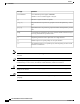
Preface This preface includes the following sections: • Audience, page ix • Conventions, page ix • Related Cisco UCS Documentation, page xi • Obtaining Documentation and Submitting a Service Request, page xi Audience To use this installation guide, you must be familiar with electronic circuitry and wiring practices and preferably be an electronic or electromechanical technician who has experience with electronic and electromechanical equipment.
Preface Conventions Text Type Indication CLI commands CLI command keywords appear in this font. Variables in a CLI command appear in this font. Note Tip [] Elements in square brackets are optional. {x | y | z} Required alternative keywords are grouped in braces and separated by vertical bars. [x | y | z] Optional alternative keywords are grouped in brackets and separated by vertical bars. string A nonquoted set of characters.
Preface Related Cisco UCS Documentation Warning IMPORTANT SAFETY INSTRUCTIONS This warning symbol means danger. You are in a situation that could cause bodily injury. Before you work on any equipment, be aware of the hazards involved with electrical circuitry and be familiar with standard practices for preventing accidents. Use the statement number provided at the end of each warning to locate its translation in the translated safety warnings that accompanied this device.
Preface Obtaining Documentation and Submitting a Service Request Cisco UCS 5108 Server Chassis Installation Guide xii OL-20035-05
CHAPTER 1 Overview This chapter contains the following sections: • System Overview, page 1 • Features and Benefits, page 2 • Components, page 4 • LEDs, page 23 System Overview The Cisco UCS 5108 server chassis and its components are part of the Cisco Unified Computing System (UCS), which uses the Cisco UCS 5108 server system with the two I/O modules and the Cisco UCS Fabric Interconnects to provide advanced options and capabilities in server and data management.
Overview Features and Benefits • Fan modules (N20-FAN5)—Eight hot-swappable fan modules • UCS B-series blade servers, including ◦Cisco UCS B200 blade servers (N20-B6620-1 for M1 or N20-B6625-1 for M2)—Up to eight half-width blade servers, each containing two CPUs and holding up to two hard drives capable of RAID 0 or 1 ◦Cisco UCS B200 M3 blade servers (UCSB-B200-M3)—Up to eight half-width blade servers, each containing two CPUs and holding up to two hard drives capable of RAID 0 or 1 ◦Cisco UCS B22 blade s
Overview Features and Benefits Feature Benefit Support for one or two Cisco UCS 2100 Series or Cisco UCS 2200 FEXes Eliminates switches from the chassis, including the complex configuration and management of those switches, allowing a system to scale without adding complexity and cost. Allows use of two I/O modules for redundancy or aggregation of bandwidth. Enables bandwidth scaling based on application needs; blades can be configured from 1.25 Gbps to 40 Gbps or more.
Overview Components Components Cisco UCS 5108 Server Chassis The Cisco UCS 5100 Series Blade Server Chassis is a scalable and flexible blade server chassis for today’s and tomorrow’s data center that helps reduce total cost of ownership. It is available configured for AC (N20-C6508) and DC (UCSB-5108-DC) power environments. Is six rack units (6 RU) high and can mount in an industry-standard 19-inch rack with square holes (such as the Cisco R Series Racks) or in round hole racks when an adapter is used.
Overview Blade Servers The midplane is an entirely passive device.
Overview Blade Servers 3 Ejector captive screw 9 Console connector 4 Hard drive bay 1 10 Reset button access 5 Hard drive bay 2 11 Beaconing LED and button 6 Power button and LED LEDs The LED indicators indicate whether the blade server is in active or standby mode, the status of the network link, the over all health of the blade server, and whether the server is set to give a flashing blue beaconing indication. See Interpreting LEDs, on page 25 for details.
Overview Blade Servers Cisco UCS B200 M3 Blade Servers For full service and installation instructions, see the Cisco UCS B200 M3 Blade Server Installation and Service Note. You can install up to eight UCS B200 M3 Blade Servers to a chassis.
Overview Blade Servers The power button and LED allows you to manually take a server temporarily out of service but leave it in a state where it can be restarted quickly. Connectors A console port gives a direct connection to a blade server to allow operating system installation and other management tasks to be done directly rather than remotely. The port uses the KVM dongle device included in the chassis accessory kit. See KVM Cable, on page 69 for more information.
Overview Blade Servers The removable hard disks also have LEDs indicating hard disk access activity and hard disk health. Buttons The Reset button is just inside the chassis and must be pressed using the tip of a paper clip or a similar item. Hold the button down for five seconds and then release it to restart the server if other methods of restarting are not working. The beaconing function for an individual server may get turned on or off by pressing the combination button and LED.
Overview Blade Servers 5 SSD 2 Fault LED 13 Power button and LED 6 Ejector lever captive screw 14 Console connector 7 Ejector lever 15 Asset tag 8 SSD sled in Bay 1 LEDs The LED indicators indicate whether the blade server is in active or standby mode, the status of the network link, the over all health of the blade server, and whether the server is set to give a flashing blue beaconing indication. See Interpreting LEDs, on page 25 for details.
Overview Blade Servers Cisco UCS B250 Blade Servers For full service and installation instructions, see the Cisco UCS B250 Blade Server Installation and Service Note.
Overview Blade Servers Connectors A console port gives a direct connection to a blade server to allow operating system installation and other management tasks to be done directly rather than remotely. The port uses the KVM dongle device included in the chassis accessory kit. See KVM Cable, on page 69 for more information. Cisco UCS B440 Blade Servers For full service and installation instructions, see the Cisco UCS B440 High Performance Blade Server Installation and Service Note.
Overview Cisco UCS B420 M3 High Performance Blade Server Buttons The Reset button is just inside the chassis and must be pressed using the tip of a paper clip or a similar item. Hold the button down for five seconds and then release it to restart the server if other methods of restarting are not working. The beaconing function for an individual server may get turned on or off by pressing the combination button and LED. See Interpreting LEDs, on page 25 for details.
Overview Adapter Cards 3 Each server has a blank plastic asset tag that pulls out of the front panel, provided so you can add your own asset tracking label without interfering with the intended air flow. LEDs The LED indicators indicate whether the blade server is in active or standby mode, the status of the network link, the over all health of the blade server, and whether the server is set to give a flashing blue beaconing indication. See Interpreting LEDs, on page 25 for details.
Overview Adapter Cards up to 128 Peripheral Component Interconnect Express (PCIe) standards-compliant virtual interfaces that can be dynamically configured so that both their interface type (network interface card [NIC] or host bus adapter [HBA]) and identity (MAC address and worldwide name [WWNN]) are established using just-in-time provisioning. In addition, the Cisco UCS M81KR supports network interface virtualization and Cisco VN-Link technology.
Overview Adapter Cards • Consolidation of LAN and SAN traffic over the same adapter card and fabric, reducing the overall number of network interface cards (NICs), HBAs, cables, and switches • Integrated management with Cisco UCS Manager Cisco UCS M71KR-Q QLogic Converged Network Adapter The Cisco UCS M71KR-Q QLogic Converged Network Adapter (CNA) is a QLogic-based Fibre Channel over Ethernet (FCoE) adapter card that provides connectivity for Cisco UCS B-Series Blade Servers in the Cisco Unified Computing
Overview Cisco UCS 2104XP FEXes Cisco UCS 2104XP FEXes Figure 8: Cisco UCS 2104 IO Module 1 4 2 3 237201 4 1 Fabric extender status indicator LED 3 Connection ports (to the fabric interconnect) 2 Link status indicator LEDs 4 Captive screws for the insertion latches Cisco UCS 2100 Series FEXes bring the unified fabric into the blade server enclosure, providing 10 Gigabit Ethernet connections between blade servers and the fabric interconnect, simplifying diagnostics, cabling, and management.
Overview Cisco UCS 2200 Series FEXes LEDs There are port activity LEDs and an LED that indicates connectivity to the servers in the chassis. Buttons No buttons are on the FEX. Connectors I/O ports support SFP+ 10 Gb Ethernet connections. There is also a console connection for use by Cisco diagnostic technicians. It is not intended for customer use.
Overview Cisco UCS 2200 Series FEXes Figure 10: Cisco UCS 2204XP FEX 1 4 2 3 237201 4 1 Fabric extender status indicator LED 3 Connection ports (to the fabric interconnect) 2 Link status indicator LEDs 4 Captive screws for the insertion latches Cisco UCS 2200 Series FEXes bring the unified fabric into the blade server enclosure, providing 10 Gigabit Ethernet connections between blade servers and the fabric interconnect, simplifying diagnostics, cabling, and management.
Overview Power Distribution Unit (PDU) LEDs There are port activity LEDs and an LED that indicates connectivity to the servers in the chassis. Buttons No buttons are on the FEX. Connectors I/O ports support SFP+ 10 Gb Ethernet connections. There is also a console connection for use by Cisco diagnostic technicians. It is not intended for customer use.
Overview Fan Modules Fan Modules The chassis can accept up to eight fan modules (N20-FAN5). A chassis must have filler plates in place if no fan will be installed in a slot for an extended period. LEDs There is one LED indication of the fan module’s operational state. See Interpreting LEDs, on page 25 for details. Buttons and Connectors No buttons or connectors are on a fan module.
Overview Power Supplies ◦The total "Maximum Draw" required to power all the components configured within that chassis—such as I/O modules, fans, blade servers (CPU and memory configuration of the blade servers). ◦The Desired Power Redundancy for the chassis. The supported power configurations are non-redundant, N+1 redundancy (or any requirement greater than N+1), and grid redundancy. To configure redundancy, see the Configuration Guide for the version of Cisco UCS Central that you are using.
Overview LEDs Note An n+1 redundant system has either two or three power supplies, which may be in any slot. Grid Redundancy The grid redundant configuration is sometimes used when you have two power sources to power a chassis or you require greater than N+1 redundancy. If one source fails (which causes a loss of power to one or two power supplies), the surviving power supplies on the other power circuit continue to provide power to the chassis.
Overview LED Locations LED Locations 192744 Figure 12: LEDs on a Cisco UCS 5108 Server Chassis—Front View Figure 13: LEDs on the Cisco UCS 5108 Server Chassis—Rear View Cisco UCS 5108 Server Chassis Installation Guide 24 OL-20035-05
Overview 192743 192743 Interpreting LEDs Interpreting LEDs Table 2: Chassis, Fan, and Power Supply LEDs LED Color Description Beaconing Off Beaconing not enabled. Blinking blue 1 Hz Beaconing to locate a selected chassis—If the LED is not blinking, the chassis is not selected. You can initiate beaconing in UCS Manager or with the button. Off No power. Amber No I/O module is installed or the I/O module is booting. Green Normal operation.
Overview Interpreting LEDs LED Color Description Fan Module Off No power to the chassis or the fan module was removed from the chassis. Amber Fan module restarting. Green Normal operation. Blinking amber The fan module has failed. Off No power to the slot. Green Normal operation. Blinking green AC power is present but the PS is either in redundancy standby mode or is not fully seated. Off Normal operation. Amber Over-voltage failure or over-temperature alarm.
Overview Interpreting LEDs Table 4: Blade Server LEDs LED Color Description Power Off Power off. Green Normal operation. Amber Standby. Off None of the network links are up. Green At least one network link is up. Off Power off. Green Normal operation. Amber Minor error. Blinking Amber Critical error. Off Inactive. Green Outstanding I/O to disk drive. Off No fault. Amber Some fault.
Overview Interpreting LEDs Cisco UCS 5108 Server Chassis Installation Guide 28 OL-20035-05
CHAPTER 2 Installation This chapter contains the following sections: • Installation Notes and Warnings for the Cisco UCS 5108 Server Chassis, page 29 • Installing the Chassis, page 35 • Repacking the Chassis, page 51 • SFP+ Transceivers, page 51 Installation Notes and Warnings for the Cisco UCS 5108 Server Chassis The following notes and warnings apply to all installation tasks: Note Warning Before you install, operate, or service the system, see the Regulatory Compliance and Safety Information for Ci
Installation Rack Requirements Warning Only trained and qualified personnel must be allowed to install, replace, or service this equipment. Statement 1030 Rack Requirements This section provides the requirements for installing in a standard open rack, assuming an external ambient air temperature range of 50 to 95°F (10 to 35°C): Note Do not use racks that have obstructions. These obstructions could impair access to field-replaceable units (FRUs). The Cisco R Series Racks are an ideal choice.
Installation Airflow Considerations server shutdowns when internal temperatures exceed specification. Use cable ties and other wiring practices to keep the rear of the chassis unobstructed as shown in the “after“ illustration. Figure 14: Cable Management After 253898 Before Airflow Considerations Airflow through the chassis is from front to back.
Installation Moving Server Chassis Moving Server Chassis When lifting the chassis, be aware of its weight, and follow these guidelines: Caution Do not try to lift the chassis using the handles on the side. These handles are intended only for moving and adjusting the chassis position. • Never lift the chassis alone—Always use two people to lift the chassis. If available, use a scissor jack or other lifting device designed for installing heavy equipment into data center racks.
Installation Required Equipment Avoid UPS types that use ferroresonant technology. These UPS types can become unstable with systems such as the Cisco UCS, which can have substantial current draw fluctuations due to fluctuating data traffic patterns. • Ensure that circuits are sized according to local and national codes. For North America, the power supply requires a 20 A circuit.
Installation Attaching the Round Hole Adapter Kit to the Rails (Optional) • ESD wrist strap • Cables with connectors (including the N20-BKVM=, which is the KVM/local I/O console dongle) • Any optional items ordered Step 3 Verify that all unused blade slots and power supply bays have blank covers. Attaching the Round Hole Adapter Kit to the Rails (Optional) Note The chassis tool-less rails are designed for racks that have square mounting holes.
Installation Installing the Chassis Step 4 Repeat steps 1to 3 for the other three adapters. Installing the Chassis This section describes how to install the chassis. This two part process consists of installing the rails into the rack and then installing the chassis into the rack and on to the rails. Caution Never attempt to lift the chassis by using an installed module’s handle as a grip point. only use the handles on the sides of the chassis.
Installation Installing the Rails Installing the Rails Procedure Step 1 Step 2 Remove the mounting template (Cisco 78-19093-01) from the accessory box. The template is designed to show you the proper holes within which the rails and cage nuts should be placed. Once the rack holes line up with the template, you should mark the holes so that their position is known after removing the template.
Installation Installing the Rails The following figure shows a rail mounted into a rack in the proper position with respect to a rack-unit boundary. Measurements are in inches between the centers of the holes. 192518 Figure 18: Installing Tool-less Chassis Support Rails into the Rack Step 4 Step 5 Step 6 Step 7 Press down firmly on the rail until the hooks seat firmly and securely into the holes, and the spring clip latches into place. Follow the same procedure to install the other rack rail.
Installation Installing the Rails plates. The next two cage nuts are installed into the fifth holes above the first cage nut. Finally, the two cage nuts are installed into the fourth holes above the second cage nuts.
Installation Installing the Round Hole Adapter Kit Cage nuts . .500 .625 .625 .250 Right rail 192730 Left rail Step 8 Remove all power supplies, fan assemblies, server blades, and fabric extenders to lighten the chassis. Even with devices removed, the chassis weighs 90 lbs (40.83 kg).
Installation Installing the Round Hole Adapter Kit Procedure Step 1 Step 2 Step 3 Step 4 Remove the mounting template (Cisco 78-19093-01) from the accessory box. The template is designed to show you the proper holes within which the rails and cage nuts should be placed. Once the rack holes line up with the template, you should mark the holes so that their position is known after removing the template.
Installation Installing the Round Hole Adapter Kit Step 5 Follow the same procedure to install the other rack rail as shown below. 279774 Figure 22: Round Hole Adapter and Rails Installed in a Rack Step 6 Step 7 Use a tape measure and level to verify that both rack rails are horizontal and at the same height. Remove all power supplies, fan assemblies, server blades, and I/O modules to lighten the chassis. Even with devices removed, the chassis weighs 90 lbs (40.83 kg).
Installation Inserting the Chassis into the Rack Inserting the Chassis into the Rack Procedure Step 1 With the help of another person (or special lifting equipment), lift the chassis and place it on the mounting rail as shown. Figure 23: Mounting Rail Weight Distribution (Square Hole Mount Shown) NON-WEIGHT BEARING SURFACECHASSIS SHOULD NOT BE RIDING ON THIS SURFACE Caution 192518 Weight bearing surface. Chassis should be riding on this surface.
Installation Inserting the Chassis into the Rack Step 2 Step 3 Slide the chassis into the rack until the front flange is flat against the cage nuts. (Cage nuts are not needed in round hole racks.) Using the six Phillips round washer head screws and the cage nuts (used in square hole installations), secure the chassis by its flanges to the rack as shown.
Installation Connecting a DC Power Supply Note Both grids in a power redundant system should have the same number of power supplies. If your system is configured for grid redundancy, slots 1 and 2 are assigned to grid 1 and slots 3 and 4 are assigned to grid 2. If only two power supplies (PS) are in a redundant- mode chassis, they should be in slots 1 and 3. Slot and cord connection numbering is shown below.
Installation Connecting a DC Power Supply Warning A readily accessible two-poled disconnect device must be incorporated in the fixed wiring. Statement 1022 Warning Use copper conductors only. Statement 1025 Warning This product requires short-circuit (overcurrent) protection, to be provided as part of the building installation. Install only in accordance with national and local wiring regulations.
Installation Connecting a DC Power Supply Note The positive and negative wires can be installed pointing either to the right or to the left as long as the terminal cover is used. The figure below shows them pointed to the right. Panduit LCD4-14A-L connectors may be used for the supply and return wires, and Panduit LCD4-14AF-L or equivalent connectors may be used for the 90-degree ground lug wire. Both connections have double lugs with .25 inch holes measuring .625 inches from center to center.
Installation Cabling Considerations for Fabric Port Channels Step 7 Replace the terminal cover as shown. This cover should always be in place when power is applied to the terminals. Step 8 Connect the other end of the power wires to a DC-power input source. Step 9 Set the DC disconnect switch in the circuit to ON. Caution In a system with multiple power supplies, connect each power supply to a separate DC power source.
Installation Proper FEX and Fabric Interconnect Port Connectivity Caution Linking a chassis to two fabric port channel port groups is disruptive and does not affect the VIF namespace unless it is manually acknowledged. The VIF namespace is then automatically set to the smaller size fabric port channel port group usage (either 63 or 118 VIFs) of the two groups. For high availability cluster mode applications, symmetric cabling configurations are strongly recommended.
Installation Proper FEX and Fabric Interconnect Port Connectivity The following figure shows an invalid connection from a FEX to two separate fabric interconnects.
Installation Removing the Chassis from a Rack ports on the fabric interconnect, the expansion modules are never used for direct chassis connections, they are used for uplink or SAN connections.
Installation Repacking the Chassis Step 2 Step 3 Step 4 Step 5 Step 6 Step 7 Disconnect the power cords and networking cables from the chassis. Remove all modules and blades from the chassis to lighten its weight. Remove the screws holding the front rack-mount flange to the rack. With two people holding the chassis, make sure that its weight is fully supported. Gently slide the chassis off the rails, and out of the rack. Replace the modules and blades in the server chassis.
Installation Optical SFP+ Transceivers The figure below shows the SFP-H10GB-CU5M transceiver. The rubber loop is used for removing the SFP+ from its port on the I/O module. 187492 Figure 30: SFP+ 10 Gb Twinax Copper Transceiver Optical SFP+ Transceivers If distances greater than 10 meters (33 feet) must be spanned, the FEX also supports the substitution of the copper SFP+ by optical SFP+ transceivers.
Installation Replacing a Copper Twinax SFP+ Transceiver with an Optical SFP+ Transceiver Replacing a Copper Twinax SFP+ Transceiver with an Optical SFP+ Transceiver Procedure Step 1 Remove the copper Twinax SFP+ from the FEX port by pulling gently on the rubber loop. The cable and SFP+ transceiver come out as a single unit, leaving the FEX port empty. 192627 Figure 31: Removing a Twinax Copper SFP+ Transceiver Step 2 Step 3 Insert the optical SFP+ transceiver into the FEX port.
Installation Replacing a Copper Twinax SFP+ Transceiver with an Optical SFP+ Transceiver Cisco UCS 5108 Server Chassis Installation Guide 54 OL-20035-05
CHAPTER 3 Installing and Removing Components This chapter describes how to remove components from the chassis and how to install components into the chassis.
Installing and Removing Components Components Note Whenever you remove a module from the chassis for an extended period of time, always replace the module with the appropriate blank panel. Failing to do so can result in heating and EMI issues. Blank panels can be ordered from Cisco Systems.
Installing and Removing Components Installing and Removing a Blade Server Note Warning 1 Front of chassis 5 Power supply slot (4 slots) 2 Chassis handle 6 FEX slot (2 slots) 3 Rear of chassis 7 Fan slots (8 slots) 4 Half-width server slot (8 slots) 8 Power Distribution Unit (PDU) slot Before you install, operate, or service the system, see the Regulatory Compliance and Safety Information for Cisco UCS for important safety information.
Installing and Removing Components Installing and Removing a Blade Server Hard Drive Caution To prevent ESD damage, wear grounding wrist straps during these procedures and handle modules by the carrier edges only. Installing a Blade Server Hard Drive Procedure Step 1 Step 2 Step 3 Place the hard drive lever into the open position by pushing the release button. Gently slide the hard drive into the opening in the blade server until it seats into place. Push the hard drive lever into the closed position.
Installing and Removing Components Installing and Removing Power Supplies Removing a Blade Server Hard Drive Procedure Step 1 Push the button to release the ejector, and then pull the hard drive from its slot. Figure 35: Pressing the Button on the Front of the Hard Drive to Deploy the Lever (Cisco UCS B200 M1 shown) 1 Step 2 Step 3 Release button 2 Hard drive lever Place the hard drive on an antistatic mat or antistatic foam if you are not immediately reinstalling it in another blade server.
Installing and Removing Components Installing a Power Supply Installing a Power Supply All power supply models (N20-PAC5-2500W, UCSB-PSU-2500ACPL, or UCSB-PSU-2500DC48) install using the same process. Procedure Step 1 Step 2 Step 3 Step 4 Step 5 Step 6 Step 7 Place the power supply’s handle in the up position.
Installing and Removing Components Removing a Power Supply Note Both grids in a power redundant system should have the same number of power supplies. If your system is configured for grid redundancy, slots 1 and 2 are assigned to grid 1 and slots 3 and 4 are assigned to grid 2. If there are only two power supplies in a redundant- mode chassis, they should be in slots 1 and 3. This would be a very unusual configuration, with a single B200 blade server in the chassis.
Installing and Removing Components Installing and Removing a Power Distribution Unit (PDU) Installing and Removing a Power Distribution Unit (PDU) Caution The Power Distribution Unit should only be replaced by a Cisco certified technician. This section is for reference only. Caution You can not hot swap a PDU (N01-UAC1). The entire chassis will need to be shut down and all power cords should be unplugged before attempting this procedure.
Installing and Removing Components Removing a PDU Removing a PDU Procedure Step 1 Step 2 Step 3 Partially remove all installed power supplies. If a power supply is seated into the PDU, removal is difficult or impossible. Loosen the captive screws. Pull the PDU clear of the chassis by pulling on the captive screws. Support its weight from below.
Installing and Removing Components Removing a FEX Configurations of 1, 2, 4, or 8 10 GB connections between FEX and Fabric interconnect are supported in UCS. If your UCS 2104XP has 4 physical connections and you want more, the next available upgrade step is the full 8 connections on the UCS 2208XP. You should verify that the FEX upgrade is completed with no problems before adding the connections for ports 5-8. If you intend to implement the Fabric port channel feature available in UCS software version 2.
Installing and Removing Components Installing a FEX Installing a FEX Procedure Step 1 Step 2 Make sure that the two levers at the front of the FEX are pulled open. Slide the FEX into the chassis slot, ensuring that the FEX is fully seated. 192601 Figure 39: Positioning a 4 Port FEX within the Server Chassis 237202 Figure 40: Positioning an 8 Port FEX within the Server Chassis Step 3 Step 4 Step 5 Close the levers and tighten the captive screw on each lever.
Installing and Removing Components Installing and Removing a Fan Module Installing and Removing a Fan Module You can hot swap a fan module (N20-FAN5) without causing an electrical hazard or damage to the system. However, you can only remove one fan module while the system is operating. Removing more than one fan module could cause overheating. Note When a fan is removed, louvers inside the chassis prevent recirculation of air into the system or loss of cooling.
Installing and Removing Components Removing a Fan Module Removing a Fan Module Procedure Step 1 Step 2 Step 3 Hold the fan module by its handle. Press down on the spring latch at the top of the fan module. Pull the fan module clear of the chassis. Note The chassis is designed to have all fan modules in place and operating at all times. Do not leave a fan module bay empty for longer than is necessary to replace it with a new fan module.
Installing and Removing Components Removing a Fan Module Cisco UCS 5108 Server Chassis Installation Guide 68 OL-20035-05
APPENDIX A Technical Specifications This appendix lists the technical specifications for the Cisco UCS 5108 server chassis and includes the following sections: • KVM Cable, page 69 • Chassis Specifications, page 70 • Environmental Specifications, page 71 • Specifications for the Cisco UCS 5108 Blade Server Chassis Power Supply Units, page 72 • Supported AC Power Cords and Plugs, page 74 KVM Cable The KVM cable (N20-BKVM) provides a connection into a Cisco UCS blade server, providing a DB9 serial connecto
Technical Specifications Chassis Specifications 2 DB9 serial connector 4 2-port USB connector for a mouse and keyboard Chassis Specifications Table 8: Cisco UCS Server Chassis Description Specification Height x Width x Depth 10.5 in (26.7 cm) x 17.5 in (44.5 cm) x 32 in (81.2 cm) Blade server slots 8 FEX slots 2 Fan module bays 8 Power supply bays 4 Backplane throughput 1.2 Tb aggregate Table 9: Weight of the Chassis Components Description Specification Empty chassis 90 lbs (40.
Technical Specifications Environmental Specifications Environmental Specifications Table 10: Environmental Specifications for the Chassis Description Specification Temperature, operating within altitude: 0 to 10,000 50 to 95°F (10 to 35°C) feet (0 to 3,000 meters) Temperature, non-operating within altitude: 0 to 40,000 feet (0 to 12,000 meters) –40 to 149°F (–40 to 65°C) Humidity (RH), noncondensing Operating: 10-90%, 28°C max.
Technical Specifications Specifications for the Cisco UCS 5108 Blade Server Chassis Power Supply Units Specifications for the Cisco UCS 5108 Blade Server Chassis Power Supply Units Table 12: AC-input Gold Power Supply (N20-PAC5-2500W) Specifications Description Specification Minimum Software requirement UCS Software Release 1.0(1) AC-input voltage 200 to 240 VAC nominal (Range: 180 to 264 VAC) AC-input frequency 50 to 60 Hz nominal (Range: 47 to 63 Hz) AC-input current 15.
Technical Specifications Specifications for the Cisco UCS 5108 Blade Server Chassis Power Supply Units Description Specification Maximum Input VA 2790 VA @ 200 VAC Maximum output power per power supply 2500 W (up to four power supplies) Maximum inrush current 35 A (sub cycle duration) Maximum Heat Output 8530 BTU Maximum hold up time 12 ms @ 2500 W Power supply output voltage 12 VDC @ 208 A Power supply standby voltage 3.
Technical Specifications Supported AC Power Cords and Plugs Item Specification Max heat dissipation 8525 BTUs/hr DC wiring must meet your local codes and regulations, we recommend using a licensed local electrician to install the DC wiring needed. To determine the number of power supply units needed for the blade server, remember that each single slot server is budgeted a max 550 W and each full width server is budgeted a max 1100 W. For a more detailed estimate, contact Cisco Sales.
Technical Specifications Continental Europe Continental Europe Power Cord Part Number—CAB-AC-2500W-EU Cord Set Rating—16A, 250 VAC Figure 44: CAB-AC-2500W-EU Power Cord for the UCS 5108 Blade Server Chassis Plug: CEE 7/7 Cordset rating: 16 A, 250 V Length: 14 ft 0 in. (4.
Technical Specifications Japan and North America Cord Set Rating—16A, 250 VAC Figure 46: CAB-AC-2500W-ISRL Power Cord for the UCS 5108 Blade Server Chassis Japan and North America Non-Locking 200 to 240 VAC operation Power Cord Part Number—CAB-AC-2500W-US1 Cord Set Rating—16A, 250 VAC Figure 47: CAB-AC-2500W-US1 Power Cord for the UCS 5108 Blade Server Chassis Plug: NEMA 6-20 Cordset rating: 20 A, 250 V Length: 14 ft 0 in. (4.
Technical Specifications Peoples Republic of China Cord Set Rating—16A, 250 VAC Figure 48: CAB-AC-C6K-TWLK Power Cord for the UCS 5108 Blade Server Chassis Plug: NEMA L6-20 Cordset rating: 20 A, 250 V Length: 14 ft 0 in. (4.
Technical Specifications Power Distribution Unit (PDU) Cord Set Rating—16A, 250 VAC Figure 50: CAB-ACS-16 Power Cord for the UCS 5108 Blade Server Chassis Cordset rating: 16 A, 250 V Length: 8 ft 2 in. (2.5 m) Plug: SEV 5934-2 Type 23 192844 Connector: IEC 60320 C19 Power Distribution Unit (PDU) Power Cord Part Number—CAB-C19-CBN Cord Set Rating—Not applicable Connector : IEC 60320 C20 Cordset r ating: 16 A, 250 V Length: 9 ft 0 in. (2.
APPENDIX B Site Planning and Maintenance Records Note For information about how to query the chassis for configuration information, see the Cisco UCS Configuration Guide.
Site Planning and Maintenance Records Site Preparation Checklist Task No.
Site Planning and Maintenance Records Contact and Site Information 8 EMI: electromagnetic interference. 9 RFI: radio frequency interference. Contact and Site Information Use the following worksheet to record contact and site information.
Site Planning and Maintenance Records Chassis and Module Information Device Serial Number Notes Blade Server–2 Blade Server–3 Blade Server–4 Blade Server–5 Blade Server–6 Blade Server–7 Blade Server–8 I/O Module-1 I/O Module-2 Note The serial numbers of all server chassis modules can be obtained using Cisco UCS Manager.
Site Planning and Maintenance Records FEX Port Connection Record FEX Port Connection Record Table 18: Chassis FEX to Fabric Interconnect Port Connection Record FEX Connected to Number Port Fabric Slot Interconnect A or B 1 Port Connection notes 1 2 3 4 5 6 7 8 2 1 2 3 4 5 6 7 8 Cisco UCS 5108 Server Chassis Installation Guide OL-20035-05 83
Site Planning and Maintenance Records FEX Port Connection Record Cisco UCS 5108 Server Chassis Installation Guide 84 OL-20035-05