
- Cisco StackPower White Paper

© 2012 Cisco and/or its affiliates. All rights reserved. This document is Cisco Public Information. Page 4 of 17
Cisco Catalyst 3750-X and 3560-X Series Switches do not consume more power than the rest of the Catalyst 3750
family of switches, but the power budget required is higher. This higher budget allows each switch to budget
enough power for the switch itself, to power a high power network module (if present), and to power its
downstream neighbor’s StackPower logic (MCU), which is the minimum number of components in a switch to form
a power stack without booting Cisco IOS Software.
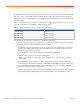
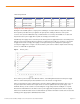
The following table shows the power budget requirement for each 3560-X and 3750-X model
Table 1. Power Budget requirements for Cisco 3560-X and 3750-X Catalyst switches
Product ID Power Budget Requirement
WS-C3560X-48 WS-C3560X-48P WS-C3750X-48 WS-C3750X-48P 223W
WS-C3560X-24 WS-C3560X-24P WS-C3750X-24 WS-C3750X-24P 190W
WS-C3750X-12S 192W
WS-C3750X-24S 230W
Note that with initial IOS release 12.2(53)SE2 all models had a power budget requirement of 206W.
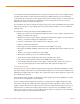
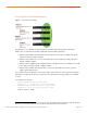
For example, a standalone Cisco Catalyst 3750-X-48P switch (Figure 3) budgets 223W, this budget does not
necessarily reflect the actual power consumption (see the data sheet for details).
Figure 3. Cisco Catalyst 3750-X-48P
Adding a new switch to a power stack
Cisco StackPower technology adds resiliency to the stack by reserving an amount of power enough to bring up the
MCU of any Catalyst3750-X Series switch. This helps ensure that if and when a new switch without any power
supplies is added to the power stack and does not have any power, it can join the power stack using the power
that has been reserved for that purpose. This guarantees the inclusion of a new switch in the power stack; if the
power stack has enough power in the power pool, Cisco StackPower will allocate power to the new switch to boot
Cisco IOS Software.
Zero-Footprint RPS
The ability to provide redundancy without the need for an actual RPS is called Zero-Footprint RPS. The power
stack discovers the members of the stack, aggregates power from all available sources in the stack, and subtracts
from the power pool an amount of power equal to the largest power supply in the stack. It does not subtract the
power supply itself nor it turn off any power supply.
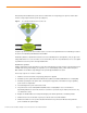
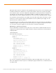
In the simplest example, a power stack is formed by using a special cable to connect switches to each other to
form a closed ring, similar to the topology for a Cisco StackWise stack (Figure 4). Up to four switches can be part
of a power stack in a ring topology, and up to nine switches can share power in a star topology by using an
eXpandable Power System (XPS) (Figure 5). Current flows through the cables that form the power stack and feed
switches in need of power or complements power requirements of other switches in the stack. It is a safe system
with plenty of circuit breakers spread around the printed circuit board to cut off current to different components in
the system or if needed, to the system itself.