ADMINISTRATION GUIDE Cisco Small Business SLM2008 8-Port Gigabit Smart Switch with PD and AC Power
CCDE, CCENT, Cisco Eos, Cisco HealthPresence, the Cisco logo, Cisco Lumin, Cisco Nexus, Cisco StadiumVision, Cisco TelePresence, Cisco WebEx, DCE, and Welcome to the Human Network are trademarks; Changing the Way We Work, Live, Play, and Learn and Cisco Store are service marks; and Access Registrar, Aironet, AsyncOS, Bringing the Meeting To You, Catalyst, CCDA, CCDP, CCIE, CCIP, CCNA, CCNP, CCSP, CCVP, Cisco, the Cisco Certified Internetwork Expert logo, Cisco IOS, Cisco Press, Cisco Systems, Cisco Systems
Contents Chapter 1: Introduction 1 Chapter 2: Getting to Know the Cisco SLM2008 Switch 2 Front Panel 2 Back Panel 3 Side Panels 3 Chapter 3: Connecting the Cisco SLM2008 Switch 5 Placement Options 5 Desktop Option 5 Wall-Mount Option 6 Connecting the Cisco SLM2008 Switch to the Network Chapter 4: Setting Up the Cisco SLM2008 Switch Launching the Web-Based Configuration Utility Navigating the Utility 7 9 9 10 System 11 Port 11 VLAN 11 Security 11 QoS 12 STP 12 Statistics 1
Contents Port 18 Configuring Port Settings 18 Configuring Static Link Aggregation 20 Configuring LACP Settings 21 Displaying LACP Status 23 VLAN 24 Configuring VLAN Settings 24 Configuring VLAN Port Settings 25 Security 27 Configuring 802.1X Settings 27 Configuring 802.
Contents Appendix A: Specifications 57 Appendix B: Where to Go From Here 60 Cisco SLM2008 8-Port Gigabit Smart Switch with PD and AC Power Administration Guide v
1 Introduction The Cisco SLM2008 8-port Gigabit Smart Switch with PD and AC Power allows you to upgrade your existing network by replacing your current workgroup hub or switch. At the same time, you can configure advanced features for security, QoS, and Spanning Tree using its web-based configuration utility. The Cisco SLM2008 switch not only allows you to upgrade to gigabit speeds but also allows you to expand your network securely.
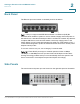
2 Getting to Know the Cisco SLM2008 Switch This chapter describes the external features of the Cisco SLM2008 8-Port Gigabit Smart Switch with PD and AC Power. The following sections are included: • Front Panel, page 2 • Back Panel, page 3 • Side Panels, page 3 Front Panel The LEDs are located on the front panel of the switch. System—(Green) Lights up when the switch is powered on. 1-8—(Green) Each LED lights up when there is a connection made through its corresponding port.
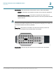
Getting to Know the Cisco SLM2008 Switch Back Panel 2 Back Panel The Ethernet ports are located on the back panel of the switch. Port 1—This port supports the IEEE 802.3af Power-over-Ethernet (PoE) PD standard, which enables a system to receive data and supply electrical power to the switch over a standard twisted-pair cable in an Ethernet network. Any 802.3afcompliant PSE device, such as a PoE switch, can directly supply power to the switch.
Getting to Know the Cisco SLM2008 Switch Side Panels 2 Reset Button—The reset button can be used to reset or reboot the switch. • Reboot—If the button is pressed for less than 10 seconds, the switch will reboot. • Restore Factory Defaults—If the button is pressed for longer than 10 seconds, the switch settings will be restored to the factory defaults and the system reboots. NOTE The switch can only be configured using the web-based utility.
3 Connecting the Cisco SLM2008 Switch This chapter will guide you through the hardware installation for the Cisco SLM2008 8-Port Gigabit Smart Switch with PD and AC Power. The following sections are included: • Placement Options, page 5 • Connecting the Cisco SLM2008 Switch to the Network, page 7 Placement Options When you choose a location for the switch, observe the following guidelines: • Make sure that the switch is accessible and that the cables can be easily connected.
3 Connecting the Cisco SLM2008 Switch Placement Options Wall-Mount Option NOTE You will need two suitable screws to mount the switch. Cisco is not responsible for damages incurred by insecure wall-mounting hardware. Suggested Mounting Hardware 4-5 mm 1-2 mm 194478 2.5-3 mm Suggested Mounting Hardware To mount the Cisco SLM2008 switch on a wall, follow these steps: STEP 1 Determine where you want to mount the switch. Ensure that the wall you use is smooth, flat, dry, and sturdy.
3 Connecting the Cisco SLM2008 Switch Connecting the Cisco SLM2008 Switch to the Network STEP 3 Insert a screw into each hole and leave 3 mm of its head exposed. STEP 4 The wall-mount slots are two crisscross slots on the bottom panel of the switch. The wall-mount slots on the switch line up with the two screws. Wall mount slots STEP 5 194450 2-1/2 Maneuver the switch to insert the screws into the two slots.
Connecting the Cisco SLM2008 Switch Connecting the Cisco SLM2008 Switch to the Network 3 NOTE When you connect your network devices, make sure you do not exceed the maximum cabling distance of 328 feet (100 meters). To connect network devices to the switch, follow these steps: STEP 1 Make sure all the devices you will connect to the switch are powered off. STEP 2 Connect a Category 5 network cable to one of the numbered ports on the switch.
4 Setting Up the Cisco SLM2008 Switch This chapter describes how to configure the Cisco SLM2008 8-Port Gigabit Smart Switch with PD and AC Power using the web-based configuration utility.
Setting Up the Cisco SLM2008 Switch Navigating the Utility 4 Login Window STEP 6 If this is your first time accessing the web-based utility, follow these steps at the login window: a. Enter admin in the Username field b. Enter admin in the Password field. c. Click Log In. For security purposes, it is recommended that you later reset your password in the System > System Settings window. If your session times out, you will need to log back into the utility.
Setting Up the Cisco SLM2008 Switch Navigating the Utility • QoS • STP • Statistics • Multicast • Admin 4 System The System Settings window is the first window displayed when you log in. • System Settings—Displays a summary of switch information. Port This window allows you to manage port settings for the switch. • Port Settings—Manually configure the speed, duplex, and flow control settings used on specific ports.
Setting Up the Cisco SLM2008 Switch Navigating the Utility 4 • 802.1X Settings—Configure security settings that include 802.1X mode, RADIUS IP, Radius UDP port, key string or Admin State authentication mode. • 802.1X Parameter—Enable re-authentication and configure the reauthentication period or EAP timeout. • Static MAC Address—Allows you to configure a switch port with the MAC address of one or more devices that are authorized to access the network through that port.
Setting Up the Cisco SLM2008 Switch Navigating the Utility 4 Multicast This window displays the multicast settings for the switch. • IGMP Settings—Configure functions that include Enable IGMP Snooping, Enable Unregistered IP Multicast Flooding, and Enable IGMP Querying. Admin This window allows you to manage the switch. • Ping—Use to see if another site on the network can be reached. • Port Mirror—Mirror traffic from any source port to a target port for realtime analysis.
5 Advanced Configuration This chapter describes how to configure the Cisco SLM2008 8-Port Gigabit Smart Switch with PD and AC Power using the web-based configuration utility. Setup The first window displayed upon login is the System Settings window. There are nine options displayed in the left panel: System, Port, VLAN, Security, QoS, STP, Statistics, Multicast, and Admin. Each option contains windows that will help you configure and manage the switch.
Advanced Configuration Using the Help System 5 Example with Help Example with Help Expanded Cisco SLM2008 8-Port Gigabit Smart Switch with PD and AC Power Administration Guide 15
5 Advanced Configuration System System Configuring System Settings The System > System Settings window displays a summary of switch information. To configure the system settings, follow these steps: STEP 1 Click System > System Settings. STEP 2 Configure the system settings. • System Name—Enter or modify the name of the switch. • System Location—Enter or modify the location name of the switch. • MAC Address—Displays the MAC address of the switch.
5 Advanced Configuration System • Default Gateway—Displays the IP address of the gateway between this device and management stations that exist on other network segments. The default value is 0.0.0.0. • DHCP Server—The IP address of the DHCP server. • Enable DHCP—When enabled, the switch will attempt to obtain an IP address from a DHCP server on your network. If an IP address is not obtained, the switch will use the IP address defined in the IP Address field below.
5 Advanced Configuration Port STEP 4 Reboot the switch by going to the Admin > Reboot window. From there, click Reboot. Port This section describes how to configure the port settings of the switch.
5 Advanced Configuration Port The Port > Port Settings window displays the current port settings of the switch. To configure port settings, follow these steps: STEP 1 Click Port > Port Settings. STEP 2 Configure the port settings. • Port—Displays the port number. • Link Status—Displays the link status of the port. • Mode—The current speed and duplex mode settings are displayed here. Auto Speed is enabled by default to allow the switch to autonegotiate the speed and duplex settings.
5 Advanced Configuration Port STEP 3 - 100 Full—Supports 100 Mbps full-duplex operation. - 1000 Full—Supports 1000 Mbps full-duplex operation. - Disabled—Disables the port. • Flow Control—Check this check box to enable flow control. • LAG—Indicates whether the port is a LAG member. • Enable Jumbo Frames—Check this check box to enable Jumbo Frame support (up to 9 KB). Click Save.
Advanced Configuration Port 5 The Port > Static Link Aggregation window displays the current static link aggregation settings. To configure static link aggregation, follow these steps: STEP 1 Click Port > Static Link Aggregation. STEP 2 LAG displays the LAG number. Select the Port numbers to add the port to the LAG group. STEP 3 Click Save.
5 Advanced Configuration Port To avoid creating a loop in the network, be sure you enable LACP before connecting the ports, and also disconnect the ports before disabling LACP. NOTE LAG port members will have to be configured with the same speed and duplex mode. A user must ensure the LAG member’s ports have the same speed and duplex settings before activating an LACP group. The Port > LACP Settings window displays the current LACP settings.
5 Advanced Configuration Port STEP 3 Click Save. Displaying LACP Status From the Port > LACP Status window, you can see the LACP status for each port, its partner port number, and operational port key. To display LACP status, follow these steps: STEP 1 Click Port > LACP Status. The following information is displayed: • LACP Port Status—LACP Status on each interface since the device was last refreshed. • Protocol Active—Indicates if the LACP is disabled or enabled on the interface.
5 Advanced Configuration VLAN STEP 2 Click Refresh to update the status information. VLAN This section describes how to configure the VLAN settings for the switch: • Configuring VLAN Settings, page 24 • Configuring VLAN Port Settings, page 25 Configuring VLAN Settings A VLAN is a group of ports that can be located anywhere in the network, but communicate as though they belong to the same physical segment.
5 Advanced Configuration VLAN The VLAN > VLAN Settings window allows you to create or delete a VLAN. To configure or change VLAN settings, follow these steps: STEP 1 Click VLAN > VLAN Settings. STEP 2 To create a single VLAN, enter the VLAN ID, and click Add. • VLAN ID—ID of configured VLAN (1-4094, no leading zeroes). STEP 3 To remove a VLAN, select the VLANs in the VLAN list, then click Delete. STEP 4 Click Save.
5 Advanced Configuration VLAN To configure VLAN Port Settings, follow these steps: STEP 1 Click VLAN > VLAN Port Settings. STEP 2 Configure the VLAN port settings by adding the required settings for each interface. • Enable Tx Force Untag—When this option is enabled, all egress frames from this port become untagged. The default value is Disable. When this function is disabled, only frames with the VLAN ID equal to the PVID will become untagged, otherwise, frames are sent with a VLAN tag.
5 Advanced Configuration Security forwarded to the VLAN based on the PVID of its ingress port. All frame types are selected by default. • STEP 3 PVID (Port VLAN identifier)—VLAN ID assigned to untagged frames received on the interface. The default value is 1. For all other VLANs, an interface must first be configured as an untagged member before you can assign its PVID to that group. Click Save. Security This section describes how to configure the security settings for the switch. • Configuring 802.
5 Advanced Configuration Security response to the switch, which it forwards to the RADIUS server. The RADIUS server verifies the client identity and sends an access challenge back to the client. The EAP packet from the RADIUS server contains not only the challenge, but the authentication method to be used. The client can reject the authentication method and request another, depending on the configuration of the client software and the RADIUS server. The authentication method must be MD5.
5 Advanced Configuration Security The Security > 802.1X Settings window displays the current 802.1X settings for the switch. To configure the 802.1X settings, follow these steps: STEP 1 Click Security > 802.1X Settings. STEP 2 In the 802.1X Settings section, enter the following information: • 802.1X Mode—Enables or disables 802.1X mode. From the drop-down menu select Enabled or Disabled. • RADIUS IP—Enter the IP address of the server. • RADIUS UDP Port—Enter the UDP Port of the server.
5 Advanced Configuration Security STEP 3 In the 802.1X Setting Table section, select the following: • STEP 4 Admin State—Select one of the following options from the drop-down menu to set the authentication mode: - Auto—Requires a dot1x-aware client to be authorized by the authentication server. Clients that are not dot1x-aware will be denied access. - Force-Authorized—Forces the port to grant access to all clients, either dot1x-aware or otherwise. (This is the default setting.
5 Advanced Configuration Security The Security > 802.1X Parameter window displays the current 802.1X parameters. To configure the 802.1X parameters, follow these steps: STEP 1 Click Security > 802.1X Parameter. STEP 2 Enter the following information: STEP 3 • Enable Reauthentication—Check the check box to enable re-authentication. • Reauthentication Period (1-3600 seconds)—Enter the time period after which a connected client must be re-authenticated. The default value is 3600 seconds.
5 Advanced Configuration Security Configuring Static MAC Address Static MAC Address allows you to configure a switch port with the MAC address of one or more devices that are authorized to access the network through that port. The MAC address is bound to the ingress port specified on the list and does not allow the MAC address to change ports. Only incoming traffic with source addresses already stored in the static address table will be accepted as authorized to access the network through that port.
5 Advanced Configuration Security STEP 3 Click Save. Configuring Management Access List The Security > Management Access List window specifies which Source IP addresses can manage the device. To configure the management access list, follow these steps: STEP 1 Click Security > Management Access List. STEP 2 Enter the following information: • Enable Management Access List—Check the check box to enable IP Access List.
5 Advanced Configuration Security STEP 3 • Management IP address 4—Enter the IP address of a fourth device that you wish to allow manage the switch. • Management IP address 5—Enter the IP address of a fifth device that you wish to allow manage the switch. Click Save. Configuring Storm Control Rate threshold is the maximum rate (packets per second) at which unknown packets are forwarded. The Security > Storm Control window displays the current rate threshold settings.
5 Advanced Configuration QoS • STEP 3 Multicast Rate—Select the storm control multicast rate threshold from the list or select the default value, No Limit. Click Save. QoS Configuring QoS Settings Network traffic is usually unpredictable and the only basic assurance that can be offered is best effort traffic delivery. To overcome this challenge, QoS is applied throughout the network.
5 Advanced Configuration QoS The QoS > QoS Settings window displays the current QoS settings. To configure the QoS settings, follow these steps. STEP 1 Click QoS > QoS Settings. STEP 2 Set the Queue Mode to Strict Priority or WRR. • Strict Priority—Services the egress queues in sequential order, transmitting all traffic in the higher priority queues before servicing lower priority queues.
5 Advanced Configuration QoS WRR Queue Mode STEP 3 From the drop-down menu, select the QoS Mode of QoS Disabled, 802.1p, Port Based, or DSCP. QoS Mode Priority Diagram DSCP Found? Yes DSCP Enabled? No Yes DSCP QoS No Yes Tagged? 802.1p Enabled? No No Yes 802.1p QoS Port QoS • 194449 Packet 802.1p—802.1p QoS Mode allows you to specify data packet priority based on the 802.1p value in VLAN priority tag of the packet. Users can map 802.1p to one of 4 priority queues.
5 Advanced Configuration QoS 802.1p QoS Mode - Prioritize Traffic—Allows you to select a traffic prioritization setting. The default value is Custom. - 802.1p Settings—The default 802.1p settings are shown in the following table: Table 1 Default 802.1p Settings 802.
5 Advanced Configuration QoS • Port-Based—Port-Based QoS mode allows you to set priority levels for each port. Port-Based QoS Mode • Port-Based Settings—This allows customization of priority levels for specific ports. By default, all ports are set to high priority. DSCP—The Cisco SLM2008 switch supports a common method of prioritizing IP traffic to meet application requirements. Traffic priorities can be mapped to one of 4 priority queues based on the Differentiated Services Code Point (DSCP) value.
5 Advanced Configuration QoS DSCP - Table 2 STEP 4 DSCP Settings—DSCP Settings enable mapping DSCP values to specific priority levels. The default DSCP settings are shown in the following table: DSCP Settings DSCP Value (0-63) Priority 46 high 34 medium 24 normal All others low • DSCP Value—Indicates the Differentiated Services Code Point value in the incoming packet. • Priority—Maps the DSCP value to the selected priority level. Click Save.
5 Advanced Configuration STP STP This section describes configuring the STP settings. • Configuring STP Settings, page 41 • Displaying STP Status, page 43 Configuring STP Settings The Spanning Tree Algorithm (STA) can be used to detect and disable network loops, and to provide backup links between switches, bridges or routers.
5 Advanced Configuration STP STEP 3 STEP 4 • System Priority—Bridge priority is used in selecting the root device, root port, and designated port. The device with the highest priority becomes the STA root device. However, if all devices have the same priority, the device with the lowest MAC address will then become the root device. From the drop-down menu, select the value. The default value is 32768. The range is 0 to 61440 in steps of 4096.
5 Advanced Configuration STP Displaying STP Status The STP > STP Status window displays the STP Status for Bridge ID and for each port. To display the STP status, follow these steps: STEP 1 Click STP > STP Status. STEP 2 The STP status information is displayed. • STP Bridge Overview - Bridge ID—A unique identifier for this bridge, consisting of the bridge priority and MAC address (where the address is taken from the switch system).
5 Advanced Configuration Statistics • Root ID—The Root ID is displayed here. STP Port Status STP Status on each interface since the device was last refreshed. STEP 3 - Port—The number of the port. - Path Cost—The best path between devices. - Port Fast—Indicates the device is the end for a switch connection. - Port State—Indicates if the STP is disabled or enabled on the interface. To update the status information, click Refresh.
5 Advanced Configuration Statistics Displaying Statistics Overview The Statistics > Statistics Overview window displays the standard statistics on network traffic for each port of the device. To display the statistics overview, follow these steps: STEP 1 Click Statistics > Statistics Overview. STEP 2 The statistics overview information is displayed. • Port—Displays the port that the data applies to. • Tx Byte—Displays the number of octets transmitted on the port since the device was last refreshed.
5 Advanced Configuration Statistics STEP 3 • Rx Errors—Displays the number of received packets with errors that have occurred on the port since the device was last refreshed. • Tx Broadcast—Displays the number of good broadcast packets transmitted on the port since the device was last refreshed. • Rx Broadcast—Displays the number of good broadcast packets received on the port since the device was last refreshed. To update the statistics information, click Refresh.
5 Advanced Configuration Multicast STEP 3 • Querier—Indicates the IGMP router is active or idle. • Queries Transmitted—Displays the number of queries that have been transmitted. • Queries Received—Displays the number of queries that have been received. • v1 Reports—Displays the number of IGMP v1 report packets that have been received by the switch. • v2 Reports—Displays the number of IGMP v2 report packets that have been received by the switch.
5 Advanced Configuration Multicast The Multicast > IGMP Settings window displays the current IGMP settings. NOTE All functions listed on the Multicast > IGMP Settings window require “Enable IGMP Snooping” to be enabled before settings will take effect. To configure the IGMP settings, follow these steps: STEP 1 Click Multicast > IGMP Settings. STEP 2 Configure the IGMP settings. • Enable IGMP Snooping—Check the check box to enable IGMP Snooping on the switch.
5 Advanced Configuration Admin STEP 3 Click Save. Admin This section describes how to configure the administration settings of the switch.
5 Advanced Configuration Admin Configuring Ping You can use a ping to see if another site on the network can be reached. Ping sends ICMP echo request packets to another node on the network. The Admin > Ping window displays the current ping settings. To configure the ping settings, follow these steps: STEP 1 Click Admin > Ping. STEP 2 Configure the Ping Parameters. STEP 3 • Target IP Address—Enter the IP address of the device you want to ping.
5 Advanced Configuration Admin Configuring Port Mirror You can mirror traffic from any source port to a target port for real-time analysis. The target port speed should match or exceed source port speed, otherwise traffic may be dropped from the monitor port. The switch supports only one mirror session. The Admin > Port Mirror window displays the current port mirror settings. To configure port mirror, follow these steps: STEP 1 Click Admin > Port Mirror. STEP 2 Configure the port mirror settings.
Advanced Configuration Admin STEP 3 5 Click Save. Restoring Factory Default The Admin > Factory Default window allows you to restore the switch’s factory default settings. To restore the switch’s factory default settings, follow these steps: STEP 1 Click Admin > Factory Default. STEP 2 Click Restore Default.
Advanced Configuration Admin 5 Rebooting the Switch The Admin > Reboot window allows you to reboot the switch. The current configuration settings are retained. To reboot the switch, follow these steps: STEP 1 Click Admin > Reboot. STEP 2 Click Reboot.
5 Advanced Configuration Admin Saving Configuration Settings The Admin > Save Configuration window allows you to save and retrieve the switch’s configuration information. When saving the configuration, there are two options: • The Configuration Upload section allows you to load a previously saved configuration file (.cfg). • The Configuration Backup section allows you to save the switch settings to a configuration file (.cfg). To load a previously saved configuration file (.
Advanced Configuration Admin 5 To save the switch settings to a configuration file (.cfg), follow these steps: STEP 1 Click Admin > Save Configuration. STEP 2 In the Configuration Backup section, click Proceed. STEP 3 Click Save when prompted to open, save, or cancel. STEP 4 Select the location where the file should be saved and click Save. Upgrading the Firmware The Admin > Firmware Upgrade window allows you to upgrade the firmware.
Advanced Configuration Admin STEP 3 Locate the appropriate file and click Open. STEP 4 Click Proceed to load the file.
A Specifications This appendix details the specifications for the Cisco SLM2008 8-Port Gigabit Smart Switch with PD and AC Power. Specifications Ports 5 RJ-45 connectors for 10BASE-T/100BASE-TX/ 1000BASE-T Auto MDI/MDI-X Autonegotiate/Manual Setting Buttons Reset Cabling Type UTP CAT 5 or better for 10BASE-T/100BASE-TX, UTP CAT 5e or better for 1000BASE-T LEDs Link/Act, System PoE 802.3af PoE-PD compatible on Port 1.
A Specifications Number of VLANs 16 Active VLANs (4096 range) VLAN Port-based and 802.1Q tag-based VLANs HOL Blocking Head of Line Blocking Prevention Management Web User Interface Built-in web UI for easy browser-based configuration Firmware Upgrade Web browser upgrade (HTTP) Port Mirroring Traffic on a port can be mirrored to another port for analysis with a network analyzer Other Management RADIUS Port Mirroring DHCP Client PING Security IEEE 802.1X 802.1X - RADIUS Authentication.
A Specifications Scheduling Priority Queuing and Weighted Round Robin (WRR) Class of Service Port-based 802.1p VLAN Priority based IPv4/v6 IP DSCP based Standards 802.3 10BASE-T Ethernet, 802.3u 100BASE-TX Fast Ethernet, 802.3ab 1000BASE-T Gigabit Ethernet, 802.3z Gigabit Ethernet, 802.3x Flow Control, 802.3 ad LACP,802.3af PoE, 802.1D STP, 802.1Q/p VLAN, 802.1X Port Access Authentication Environmental Dimensions WxHxD 5.12 in. x 1.12 in. x 5.12 in. 130 mm x 28.5 mm x 130 mm Unit Weight 0.84 lb (0.
B Where to Go From Here Cisco provides a wide range of resources to help you and your customer obtain the full benefits of the Cisco SLM2008 8-Port Gigabit Smart Switch with PD and AC Power. Product Resources Support Cisco Small Business Support Community www.cisco.com/go/smallbizsupport Online Technical Support www.cisco.com/support and Documentation (Login Required) Phone Support Contacts www.cisco.com/en/US/support/ tsd_cisco_small_ business_support_center_contacts.
B Where to Go From Here Cisco Small Business Home www.cisco.com/smb Marketplace www.cisco.