ADMINISTRATION GUIDE Cisco Small Business RV320/RV325 Gigabit Dual WAN VPN Router
78-20928-02
Contents Chapter 1: Getting Started 7 Using the Getting Started Window 7 Features of the User Interface 8 Chapter 2: System Summary 11 System Information 11 Configuration (Wizard) 12 Port Activity 12 IPv4 and IPv6 13 Security Status 14 VPN Setting Status 14 SSL VPN Status 15 Log Setting Status 15 Chapter 3: Setup 17 Setup Network 17 IP Mode 17 WAN1 or WAN2 Port Settings 18 USB1 or USB2 Port Settings 28 3G/4G Connection 28 Setting Failover and Recovery 29 DMZ Enable 31
Contents Advanced Routing 41 Configuring Dynamic Routing 41 Configuring Static Routing 42 Inbound Load Balance 43 USB Device Update 44 Chapter 4: DHCP 45 DHCP Setup 46 Viewing the DHCP Status 48 Option 82 49 IP and MAC Binding 50 DNS Local Database 51 Router Advertisement (IPv6) 52 Chapter 5: System Management 55 Dual WAN Connections 55 Bandwidth Management 57 SNMP 59 Configuring SNMP 59 Discovery-Bonjour 61 LLDP Properties 62 Using Diagnostics 63 Factory Default 63
Contents Port Status 70 Traffic Statistics 71 VLAN Membership 71 QoS:CoS/DSCP Setting 72 DSCP Marking 72 802.
Contents Chapter 10: Log 107 System Log 107 System Statistics 110 Processes 110 Chapter 11: SSL VPN 111 Status 112 Group Management 112 Resource Management 115 Advanced Setting 116 Chapter 12: Wizard 117 Basic Setup 117 Access Rule Setup 117 Chapter 13: User Management Cisco Small Business RV320/RV325 Administration Guide 119 6
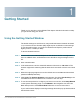
1 Getting Started Thank you for choosing a Cisco RV320. This chapter includes information to help you get started using your device. Using the Getting Started Window The default settings are sufficient for many small businesses. Network demands or your Internet Service Provider (ISP) might require modification of the settings. To use the web interface, you need a PC with Internet Explorer (version 6 and higher), Firefox, or Safari (for Mac).
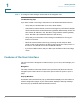
1 Getting Started Features of the User Interface STEP 7 To configure other settings, use the links in the navigation tree. Troubleshooting Tips If you have trouble connecting to the Internet or the web-based web interface: • Verify that your web browser is not set to Work Offline. • Check the local area network connection settings for your Ethernet adapter. The PC should obtain an IP address through DHCP. Alternatively, the PC can have a static IP address in the 192.168.1.
Getting Started Features of the User Interface 1 Help To view information about the selected configuration page, click Help near the top right corner of the web interface. If your web browser displays a warning message about the pop-up window, allow the blocked content. Logout To exit the web interface, click Logout near the top right corner of the web interface. The Login page appears.
1 10 Getting Started Features of the User Interface Cisco Small Business RV320/RV325 Administration Guide
2 System Summary The System Summary displays information about the current status of the device connections, status, settings, and logs. System Information System information descriptions: • Serial Number—Serial number of the device. • Firmware version—Version number of the installed firmware. • PID VID—Version number of the hardware. • MD5 Checksum—A value used for file validation. • LAN IPv4/ Subnet Mask—IPv4 management IP address and subnet mask of the device.
2 System Summary Configuration (Wizard) Configuration (Wizard) To access the Internet connection setup wizard and be prompted through the process, click Setup Wizard to launch the Wizard. Port Activity Port Activity identifies the port interfaces and indicates the status of each port: • Port ID—Port label. • Interface—Type of interface: LAN, WAN, or DMZ. Multiple WAN interfaces are indicated by a number, such as WAN1 or WAN2.
2 System Summary IPv4 and IPv6 • VLAN—VLAN ID of this port. There are two predefined VLANs: 25 and 100. VLAN 25 can be used for guest VLAN access and VLAN 100 can be used for Voice traffic. By default, VLAN 25 and VLAN 100 are not enabled. • Receive Packet Count—Number of packets received on this port. • Receive Packet Byte Count—Number of bytes received on this port. • Transmit Packet Count—Number of packets transmitted by this port.
2 System Summary Security Status Security Status This section displays the status of the security features: • SPI (Stateful Packet Inspection)—Status of the firewall: On (green) or Off (red). Tracks the state of network connections, such as TCP streams and UDP communication, traveling across it. The firewall distinguishes legitimate packets for different types of connections. Only packets matching a known active connection are allowed past the firewall; other packets are rejected.
2 System Summary SSL VPN Status • PPTP Tunnel(s) Used—Point-to-Point Tunneling Protocol (PPTP) tunnels in use. PPTP is a method for implementing virtual private networks. PPTP uses a control channel over TCP and a Generic Routing Encapsulation (GRE) tunnel to encapsulate PPP packets. • PPTP Tunnel(s) Available—PPTP tunnels available.
2 16 System Summary Log Setting Status Cisco Small Business RV320/RV325 Administration Guide
3 Setup Use the Setup > Network page to set up your LAN, WAN (Internet), DMZ, and so forth. Setup Network To open the Network page, click Setup > Network. Some ISPs require that you assign a hostname and domain name to identify your device. Default values are provided, but they can be changed as needed: • Host Name—Keep the default setting or enter a hostname specified by your ISP. • Domain Name—Keep the default setting or enter a domain name specified by your ISP.
3 Setup Setup Network Adding or Editing an IPv4 Network By default one IPv4 LAN subnetwork is configured, 192.168.1.1. One subnetwork is usually sufficient for most small businesses. The firewall denies access if a LAN device source IP address is on a subnetwork that is not specifically allowed. You can allow traffic from other subnetworks and use this device as an edge router that provides Internet connectivity to a network. STEP 1 Click the IPv4 tab to display the Multiple Subnet table.
3 Setup Setup Network To configure WAN Connection Settings, select a WAN interface and click Edit. WAN Connection Settings appears. Select the WAN Connection Type from the menu and modify the related parameters as described in these sections: Obtain an IP Automatically Choose this option if your ISP dynamically assigns an IP address to the device. (Most cable modem subscribers use this connection type.) The ISP assigns the device IP address for this port, including the DNS server IP addresses.
3 Setup Setup Network - Configure to RA and DHCPv6 automatically—Provide Stateless and Stateful IPv6 addresses for LAN-side PCs. Static IP Choose this option if your ISP assigned a permanent IP address to your account. Enter the settings provided by your ISP: • Specify WAN IP Address—IP address that your ISP assigned to your account. • Subnet Mask (IPv4)—Subnetwork mask. • Default Gateway Address—IP address of the default gateway. To specify a DNS server, enter the IP address of DNS Server 1.
3 Setup Setup Network PPPoE Choose this option if your ISP uses PPPoE (Point-to-Point Protocol over Ethernet) to establish Internet connections (typical for DSL lines). Then enter the settings provided by your ISP: • Username and Password—Username and password for your ISP account. The maximum number of characters for each entry is 255. • Service Name—A set of services provided by the ISP identified by the service name. • Connection Timers—Connection is disconnected after a period of inactivity.
3 Setup Setup Network To configure the IPv6 parameters, check Enable. The DHCPv6 client process and requests for prefix delegation through the selected interface are enabled. Use this option when your ISP is capable of sending LAN prefixes by using DHCPv6. If your ISP does not support this option, manually configure a LAN prefix: NOTE When DHCP-PD is enabled, manual LAN IPv6 addressing is disabled. When DHCP- PD is disabled, manual LAN IPv6 addressing is enabled.
3 Setup Setup Network • • Connection Timers—Connection is disconnected after a period of inactivity. - Connect on Demand—When this feature is enabled, the device automatically establishes your connection. If you enabled this feature, enter the Max Idle Time, the number of minutes that the connection can be inactive before the connection is terminated. The default maximum idle time is 5 minutes. - Keep Alive—Ensures that your router is always connected to the Internet.
3 Setup Setup Network Stateless Address Autoconfiguration (IPv6) Choose this option if your ISP uses IPv6 Router Solicitations and Router Advertisements, hosts on the network learn which network they are connected to, and once they do, they can automatically configure a host ID on that network. To specify a DNS server, enter the IP address of DNS Server 1. Optionally, you can enter a second DNS server. The first available DNS server is used.
3 Setup Setup Network IPv6 in IPv4 Tunnel (IPv6) Choose this option if your ISP uses IPv6 in IPv4 Tunnel to establish Internet connections. You must enter an IPv4 Static IP address. Then enter the settings provided by your ISP: • Local IPv6 Address—Local IPv6 address for your ISP account. • Remote IPv4 Address—Remote IPv4 address for your ISP account. • Remote IPv6 Address—Remote IPv6 address for your ISP account. • DNS Server 1 and DNS Server 2—IP addresses of the DNS servers.
3 Setup Setup Network 6to4 Tunnel (IPv6) Choose this option to establish an auto-tunnel in an IPv4 network (or real IPv4 Internet connection) across two independent IPv6 networks. Enter the following parameters: Relay IPv4 Address—Allows a 6to4 host to communicate with the native IPv6 Internet. It must have a IPv6 default gateway set to a 6to4 address that contains the IPv4 address of a 6to4 relay router. To avoid the need for users to set this up manually, the anycast address of 192.88.99.
3 Setup Setup Network IPv6 Rapid Deployment (6rd) Tunnel (IPv6) Choose this option if your ISP uses 6rd Tunnel (IPv6 Rapid Deployment) to establish Internet connections. Enter the settings provided by your ISP. • 6rd Configuration Mode: - Manual—Manually set 6rd Prefix, Relay IPv4 Address, and IPv4 Mask Length as provided by your ISP. - Auto (DHCP)—Use DHCP (option 212) to obtain 6rd Prefix, Relay IPv4 Address, and IPv4 Mask Length. • 6rd Prefix—6rd Prefix for your ISP account.
3 Setup Setup Network USB1 or USB2 Port Settings USB port configuration manages the connection between this device and the USB dongle. It also manages WAN port failover (redundancy). Some USB dongles configure their credentials automatically. Others, such as the Verizon UML290VW 4G dongle, require manual configuration. Refer to the manufacturer's documentation for the dongle for more information.
3 Setup Setup Network Setting Failover and Recovery While both an Ethernet and mobile network link might be available, only one connection at a time can be used to establish a WAN link. Whenever one WAN connection fails, the device attempts to bring up another connection on another interface. This feature is called Failover. When the primary WAN connection is restored, it reverts to that path and drops the backup connection. This feature is called Recovery.
3 Setup Setup Network - Extra Charge—Cost in dollars if a given period of time is exceeded. - Stop connection...—Check to enable dropping the connection when the time exceeds the given time. The window appears: • Previous Cumulative Time—Amount of time the 3G/4G connection has been up since being reset. • Current Cumulative Time—Amount of time that has elapsed since the device brought up a 3G/4G connection. • Charge—Estimated cost of the connection since the counters were reset.
3 Setup DMZ Enable DMZ Enable A DMZ is a subnetwork that is open to the public but behind the firewall. A DMZ allows you to redirect packets coming into your WAN port to a specific IP address in your LAN. You can configure firewall rules to allow access to specific services and ports in the DMZ from both the LAN or WAN. In the event of an attack on any of the DMZ nodes, the LAN is not necessarily vulnerable.
3 Setup Password ! CAUTION The password cannot be recovered if it is lost or forgotten. If the password is lost or forgotten, the device must be reset to the factory default settings, removing all configuration changes. If you are accessing the device remotely and reset the device to factory defaults, you cannot log into the device until you have established a local, wired link on the same subnetwork. After changing the username or password, you are logged out.
3 Setup Time Minimum number of character classes Enter the number of classes that the password must include. By default, the password must contain characters from at least three of these classes: • Uppercase letters • Lowercase letters • Numbers • Special characters available on a standard keyboard The new password must be different than the current one Check Enable if the new password must be differerent from the current password.
3 Setup DMZ Host To configure NTP and time settings, choose Setup > Time. • Time Zone—Time zone relative to Greenwich Mean Time (GMT). • Daylight Savings Time—Enable or disable the adjustment for daylight savings time. Enter the start date in the From fields and enter the stop date in the To fields. • Set Date and Time—Auto enables the NTP server. If you chose Auto, enter the fully qualified NTP Server name or IP address.
3 Setup (Port) Forwarding Use this function to establish a web server or FTP server. Make sure that you enter a valid IP address. (To run an Internet server, it might be necessary to use a static IP address.) For added security, outside users are able to communicate with the server, but they are not allowed to connect to network devices. To add or edit a service to the table: STEP 1 To add a service, click Add in the Port Range Forwarding table. To edit a service, select the row and click Edit.
3 Setup (Port) Forwarding • Port Range—Range of port numbers reserved for this service. STEP 4 Click Save. Configuring Port Triggering Port triggering allows the device to monitor outgoing data for specific port numbers. The IP address of the client that sent the matching data is remembered by the device. When the requested data returns through the device, the data is transmitted to the proper client by using IP addressing and port mapping rules.
3 Setup Port Address Translation Port Address Translation Port Address Translation (PAT) is an extension of Network Address Translation (NAT) that permits multiple devices on a LAN to be mapped to a single public IP address to conserve IP addresses. PAT is similar to port forwarding except that an incoming packet with destination port (external port) is translated to a packet different destination port (an internal port). The Internet Service Provider (ISP) assigns a single IP address to the edge device.
3 Setup Setting Up One-to-One NAT Adding or Editing a Service Name To add or edit an entry on the Service list: STEP 1 Click Service Management. If the web browser displays a warning about the pop-up window, allow the blocked content. STEP 2 To add a service, click Add in the Service Management table. To edit a service, select the row and click Edit. The fields are open for modification. If the web browser displays a warning about the pop-up window, allow the blocked content.
3 Setup MAC Address Cloning To enable this feature, check Enable. To add an entry to the list, click Add and enter the following information: • Private Range Begin—Starting IP address of the internal IP address range that you want to map to the public range. Do not include the router management IP address in this range. • Public Range Begin—Starting IP address of the public IP address range provided by the ISP. Do not include the router WAN IP address in this range.
3 Setup Assigning Dynamic DNS to a WAN Interface Assigning Dynamic DNS to a WAN Interface Dynamic Domain Name System (DDNS) service assigns a fixed domain name to a dynamic WAN IP address, so you can host your own web, FTP, or another type of TCP/IP server on your LAN. Select this feature to configure the WAN interfaces with your DDNS information. Before configuring Dynamic DNS on the router, we recommend that you visit www.dyndns.org and register a domain name. (The service is provided by DynDNS.org).
3 Setup Advanced Routing Advanced Routing This feature enables dynamic routing and adds static routes to the routing table for IPv4 and IPv6. To view the routing table, click View Routing Table. Click Refresh to update the data. Click Close to close the pop-up window. Configuring Dynamic Routing Dynamic routing constructs routing tables automatically, based on information carried by routing protocols, and allowing the network to act nearly autonomously in avoiding network failures and blockages.
3 Setup Advanced Routing (VLSM). RIPv1 also lacks support for router authentication, making it vulnerable to attacks. RIPv2 carries a subnet mask and supports password authentication security. • Transmit RIP versions—Select the RIP protocol for transmitting network data: None, RIPv1, RIPv2 - Broadcast, or RIPv2 - Multicast. RIPv2 - Broadcast (recommended) broadcasts data in the entire subnet. RIPv2 - Multicast sends data to multicast addresses.
3 Setup Inbound Load Balance To delete an entry from the list, click the entry that you want to delete, and then click Delete. To view current data, click View Routing Table. The Routing Table Entry List appears. You can click Refresh to update the data, or click Close to close the pop-up window. Inbound Load Balance Inbound load balancing distributes inbound traffic equally to every WAN port to make best use of bandwidth. It also can prevent traffic from unequal distribution and congestion.
3 Setup USB Device Update STEP 6 Click SPF Settings to add SPF text. SPF (Sender Policy Framework) is an email validation system that prevents email spam by detecting email spoofing (a common vulnerability) by verifying sender IP addresses. (Configuring this field is not required. More information can be found at http://www.openspf.org/Tools#wizard?mydomain=&x=35&y=6.) STEP 7 Enter the Mail Server parameters: • Host Name—Name (without the domain name) of mail host. • Weight—Order of the mail hosts.
4 DHCP Dynamic Host Configuration Protocol (DHCP) is a network protocol that is used to configure network devices to communicate on an IP network. A DHCP client uses the DHCP protocol to acquire configuration information, such as an IP address, a default route, and one or more DNS server addresses from a DHCP server. The DHCP client then uses this information to configure its host. Once the configuration process is complete, the host is able to communicate on the Internet.
4 DHCP DHCP Setup DHCP Setup DHCP Setup configures DHCP for IPv4 or IPv6. It also allows some devices to download their configuration from a TFTP server. When a device starts, if it does not have both the IP address and TFTP server IP address pre configured, it sends a request with Option 66, 67, and 150 to the DHCP server to obtain this information. DHCP Option 150 is Cisco proprietary. The IEEE standard that similar to this requirement is Option 66.
4 DHCP DHCP Setup • Client Lease Time—Amount of time in minutes that a network user is allowed to connect to the router with the current IP address. Valid values are 5 to 43200 minutes. The default is 1440 minutes (equal to 24 hours). • Range Start and Range End—Starting and ending IP addresses that create a range of IP addresses that can be assigned dynamically. The range can be up to the maximum number of IP addresses that the server can assign without overlapping features such as PPTP and SSL VPN .
4 DHCP Viewing the DHCP Status • DHCP Relay—Passes DHCP requests and replies from another DHCP server through the device. • Client Lease Time—Amount of time that a network user is allowed to connect to the router with the current IP address. Enter the amount of time in minutes. Valid values are 5 to 43200 minutes. The default is 1440 minutes (equal to 24 hours). • DNS Server 1 and DNS Server 2—(Optional) IP address of a DNS server.
4 DHCP Option 82 • DHCP Available—Number of dynamic IP addresses available. • Total—Total number of dynamic IP addresses managed by the DHCP server. The Client Table shows the DHCP client information: • Client Host Name—Name assigned to a client host. • IP Address—Dynamic IP address assigned to a client. • MAC Address (IPv4 only)—MAC address of a client. • Client Lease Time—Amount of time that a network user can remain connected to the router with a dynamic IP address.
4 DHCP IP and MAC Binding IP and MAC Binding When the device is configured as a DHCP server or for DHCP relay, you can bind static IP addresses to up to 100 network devices, such as a web server or an FTP server. Binding does not assign an IP address to a device. You should ensure that each device bound to a static IP address in the IP & MAC binding table is configured to use a static IP address.
4 DHCP DNS Local Database Edit or Delete Bound Entries To Edit the settings, select an entry in the list and click Edit. The information appears in the text fields. Make the changes, and click Save. To Delete an entry from the list, select the entry to delete, and click Delete. To select a block of entries, click the first entry, hold down the Shift key, and click the final entry in the block. To select individual entries, press the Ctrl key while clicking each entry.
4 DHCP Router Advertisement (IPv6) To change the TCP/IP connection settings, for example, on a PC running Windows, go to the Local Area Connection Properties > Internet Protocol > TCP/IP Properties window. Choose Use the following DNS server address, and enter the LAN IP address of the router as the Preferred DNS Server. For more information, refer to the documentation for the client that you are configuring.
4 DHCP Router Advertisement (IPv6) enter the Advertisement Interval; the interval at which Router Advertisement messages are sent. Enter any value between 10 and 1800 seconds. The default is 30 seconds. • Unicast only—Send Router Advertisement messages only to wellknown IPv6 addresses. RA Flags—Determines whether or not hosts can use DHCPv6 to obtain IP addresses and related information.
4 54 DHCP Router Advertisement (IPv6) Cisco Small Business RV320/RV325 Administration Guide
5 System Management System Management configures advanced settings, such as diagnostic tools, and performs tasks such as firmware upgrades, backups, and device reboots. Dual WAN Connections Use this feature to configure the settings for your Internet connections, if you are using more than one WAN interface. To configure the WAN ports, select System Management > Dual WAN in the navigation tree.
5 System Management Dual WAN Connections • Downstream—Maximum downstream bandwidth provided by your ISP. The default is 10000 kbs. Network Service Detection Optionally, check the box to allow the device to detect network connectivity by pinging specified devices and enter the settings as described here: • Retry count—Number of times to ping a device. The range is 1 to 99999 and the default is 3. • Retry timeout—Number of seconds to wait between pings.
5 System Management Bandwidth Management To enable the protocol binding, check the box to enable this rule, or uncheck the box to disable it. To Edit the settings, select an entry in the list. The information appears in the text fields. Make the changes, and click Save. To Delete an entry from the list, select the entry to delete, and click Delete. To select a block of entries, click the first entry, hold down the Shift key, and click the final entry in the block.
5 System Management Bandwidth Management Maximum Bandwidth Provided by ISP Enter the maximum bandwidth settings as specified by your ISP: • Upstream—Maximum upstream bandwidth provided by your ISP. • Downstream—Maximum downstream bandwidth provided by your ISP. Bandwidth Management Type Choose one of the following management options: • Rate Control—Minimum (guaranteed) bandwidth and maximum (limited) bandwidth for each service or IP address. You can add up to 100 services.
5 System Management SNMP • Priority—Choose the priority for this service: High or Low. Default priority level is Medium, which is implied and not shown in the web interface. Check the box to enable this service. To Edit the settings, select an entry in the list and click Edit. The information appears in the text fields. Make the changes, and click Save. To Delete an entry from the list, select the entry to delete, and click Delete.
5 System Management SNMP • Trap Community Name—Password sent with each trap to the SNMP manager. The string can be up to 64 alphanumeric characters. The default is public. • Enable SNMPv1/v2c—Enables SNMP v1/v2c. • - Get Community Name—Community string for authenticating SNMP GET commands. You can enter a name up to 64 alphanumeric characters in length. The default is public. - Set Community Name—Community string for authenticating SNMP SET commands.
5 System Management Discovery-Bonjour STEP 5 Click Save. To add or edit a user: STEP 1 Click Add or select a user and click Edit in the User Table. STEP 2 Enter the User Name. STEP 3 Select the Group from the drop-down menu. STEP 4 Select the Authentication Method and enter the Authentication Password. STEP 5 Select the Privacy Method and enter the Privacy Password. STEP 6 Click Save.
5 System Management LLDP Properties LLDP Properties Link Layer Discovery Protocol (LLDP) is a vendor-neutral protocol in the Internet Protocol Suite used by network devices for advertising their identity, capabilities, and neighbors on an IEEE 802 local area network, principally wired Ethernet. LLDP information is sent by devices from each of their interfaces at a fixed interval, in the form of an Ethernet frame. Each frame contains one LLDP Data Unit (LLDPDU).
5 System Management Using Diagnostics Using Diagnostics The Diagnostic page accesses two built-in tools, DNS Name Lookup and Ping. If you suspect a problem with connectivity, you can use these tools to investigate the cause. To open this page, select System Management > Diagnostic. To use DNS to learn an IP address, choose DNS Lookup, enter the Lookup Domain Name , such as www.cisco.com, and click Go. The IP address is displayed.
5 System Management Firmware Upgrade Firmware Upgrade This feature downloads the firmware for your device from a PC or a USB Flash drive and installs it. The window displays the Firmware Version currently running on the device. NOTE If you choose an earlier version of the firmware, the device might reset to factory default values. We recommend that you backup your configuration by using the Backup and Restore procedure before updating the firmware. Upgrading the firmware might take several minutes.
5 System Management Restart Alternatively, you can choose a language in the following ways: • On the Login page, choose a language from the Language drop-down list. • On all configuration pages, choose a language from the drop-down list at the top right-hand corner. For firmware versions 1.0.2.03 or earlier, use the Language Setup page to choose a new language by uploading a language pack to your device. STEP 1 Navigate to System Management > Language Setup.
5 System Management Backup and Restore Backup and Restore Configuration files can be imported, exported, and copied. The router has two managed configuration files, startup and mirror. The device loads the startup file from memory when it boots up into the running configuration and copies the startup file to the mirror file. Thus, the mirror file contains the last known valid configuration. If the Startup configuration file is corrupted or fails for any reason, the mirror configuration file is used.
5 System Management Backup and Restore STEP 3 Click Save and choose a file location. Optionally, enter a filename and click Save. TIP The default filenames are Startup.config and Mirror.config. The .config extension is required. For easier identification, it might be helpful to enter a filename that includes the current date and time. Copying the Mirror File to the Startup File You can manually copy the device startup configuration file to the mirror configuration file.
5 68 System Management Backup and Restore Cisco Small Business RV320/RV325 Administration Guide
6 Port Management Use Port Management to configure port settings and view the status of the port. You can enable port mirroring, disable a port, or set the priority, speed, duplex mode, and auto-negotiation. You also can enable port-based VLANs to control traffic between devices on your network. Configuring the Ports You can set port mirroring and manage ports, including priority and mode. Port mirroring sends a copy of network packets seen on one port to a network monitoring connection on another port.
6 Port Management Port Status • Disable—Check this box to disable a port. By default, all ports are enabled. • EEE—Check this box to enable Energy-Efficient Ethernet that reduces the consumption of power during periods of low data activity. • Priority—For each port, select the appropriate priority level, High or Normal. This ensures Quality of Service (QoS) by prioritizing the traffic for devices on particular ports.
6 Port Management Traffic Statistics Traffic Statistics To open this page, select Port Management > Traffic Statistics in the navigation tree. For the selected port, the Statistics table displays the following: • Port ID—Location of the port. • Link Status—Status of the connection. • Rx Packets—Number of packets received on the port. • Rx Packets—Number of packet received, measured in bytes. • Tx Packets—Number of packets sent on the port. • Tx Packets—Number of packet sent, measured in bytes.
6 Port Management QoS:CoS/DSCP Setting QoS:CoS/DSCP Setting This option groups traffic by classes of service (CoS), ensuring bandwidth and higher priority for the specified services. All traffic that is not added to the IP Group uses Intelligent Balancer mode. To open this page, select Port Management > QoS:CoS/DSCP Setting in the navigation tree. To configure the service queues, select the Queue priority (4 is the highest and 1 is the lowest) from the drop-down menu.
6 Port Management 802.1X Configuration 802.1X Configuration Port-based network access control uses the physical access characteristics of IEEE 802 LAN infrastructures to provide a means of authenticating and authorizing devices attached to a LAN port that has point-to-point connection characteristics, and of preventing access to that port in cases which the authentication and authorization fails. A port in this context is a single point of attachment to the LAN infrastructure.
6 74 Port Management 802.
7 Firewall The primary objective of a firewall is to control the incoming and outgoing network traffic by analyzing the data packets and determining whether it should be allowed through or not, based on a predetermined rule set. A network firewall builds a bridge between an internal network that is assumed to be secure and trusted and another network, usually an external (inter)network such as the Internet that is assumed not to be secure and untrusted.
7 Firewall Access Rules • Remote Management—Allows remote management of the device when enabled. The port is 443 by default. It can be changed to any user-defined port. The string will be https://: • Multicast Pass Through—Allows multicast messages to pass through the device. • HTTPS—Hypertext Transfer Protocol Secure is a communications protocol for secure communication over a computer network, with especially wide deployment on the Internet.
7 Firewall Access Rules Adding an Access Rule to the IPv4 Access Rule Table To add (or edit) an IPv4 access rule: STEP 1 Click the IPv4 tab. STEP 2 Click Add (or select the row and click Edit). STEP 3 Select the Action, Allow or Deny, for this rule from the drop-down menu. STEP 4 Select a Service from the drop-down menu. STEP 5 Select Log packets matching this rule or No Log. STEP 6 Select the Source Interface from the drop-down menu. STEP 7 Select the Source IP address from the drop-down menu.
7 Firewall Content Filter STEP 6 Select the Source Interface from the drop-down menu. STEP 7 Select the Source IP Prefix Length from the drop-down menu. If you selected Single, enter the source IP prefix. If you selected Range, enter the starting IP prefix and the prefix length. STEP 8 Select the Destination Prefix Length from the drop-down menu. If you selected Single, enter the destination IP prefix. If you selected Range, enter the starting IP prefix and the prefix length. STEP 9 Click Save.
7 Firewall Content Filter STEP 3 Enter a word in the Keyword column. STEP 4 Click Save. Accepting Allowed Domains To specifically accept a domain: STEP 1 Select Accept Allowed Domains. STEP 2 Click Add (or Edit) in the Allowed Domains table. STEP 3 Enter the name in the Domain Name column. STEP 4 Click Save. Scheduling The restrictions can be scheduled for a specific time on selected days. To schedule time and days: STEP 1 Select the Time from the drop-down menu.
7 80 Firewall Content Filter Cisco Small Business RV320/RV325 Administration Guide
8 VPN A VPN is a connection between two endpoints in different networks that allows private data to be sent securely over a shared or public network, such as the Internet. This tunnel establishes a private network that can send data securely by using industry-standard encryption and authentication techniques to secure the data sent. Summary This feature displays general information about the VPN tunnel settings. The device supports up to 100 tunnels.
8 VPN Summary • Domain Name 1 through 4—If this router has a static IP address and a registered domain name, such as MyServer.MyDomain.com, enter the Domain Name to use for authentication. A domain name can be used only for one tunnel connection. The VPN Tunnel Status displays the number of Tunnels Used, Tunnels Available, Tunnels Enabled, and Tunnels Defined.
8 VPN Gateway to Gateway • Remote Client—IP address and subnet mask of the Remote Client. • Details—IP address of the Remote Gateway. • Tunnel Test—Status of the VPN tunnel. Gateway to Gateway In a site-to-site or gateway-to-gateway VPN, the local router at one office connects to a remote router through a VPN tunnel. Client devices can access network resources as if they were all at the same site. This model can be used for multiple users at a remote office.
8 VPN Gateway to Gateway • Enable—Check this box to enable the VPN tunnel, or uncheck it to disable the tunnel. By default, the tunnel is enabled. Local Group Setup Enter the settings for the Local Group Setup for this router. (Mirror these settings when configuring the VPN tunnel on the other router. ) NOTE All the options are documented, but only those options that relate to the selected parameter display.
8 VPN Gateway to Gateway - Dynamic IP + E-mail Addr.(USER FQDN) Authentication—This router has a dynamic IP address and does not have a Dynamic DNS hostname. Enter an Email Address to use for authentication. If both routers have dynamic IP addresses (as with PPPoE connections), do not choose Dynamic IP + Email Addr. for both gateways. For the remote gateway, choose IP Address and IP Address by DNS Resolved.
8 VPN Gateway to Gateway Remote Group Setup Enter the settings for the Remote Group Setup for this router: • 86 Remote Security Gateway Type—Method for identifying the router to establish the VPN tunnel. The Remote Security Gateway is the other router. At least one of the routers must have either a static IP address or a dynamic DNS hostname to make a connection. - IP Only—Static WAN IP address. If you know the IP address of the remote VPN router, choose IP Address, and enter the address.
8 VPN Gateway to Gateway • Local Security Group Type—LAN resources that can use this tunnel. The Local Security Group is for this router’s LAN resources; the Remote Security Group is for the other router’s LAN resources. - IP Address—Specify one device that can use this tunnel. Enter the IP Address of the device. - Subnet—Allow all devices on a subnet to use the VPN tunnel. Enter the subnetwork IP Address and Subnet Mask. - IP Range—A range of devices that can use the VPN tunnel.
8 VPN Gateway to Gateway • Perfect Forward Secrecy—When Perfect Forward Secrecy (PFS) is enabled, IKE Phase 2 negotiation generates new key material for IP traffic encryption and authentication, so hackers using brute force to break encryption keys will not be able to obtain future IPsec keys. Check the box to enable this feature, or uncheck the box to disable this feature. This feature is recommended. • Preshared Key—Preshared key to use to authenticate the remote IKE peer.
8 VPN Gateway to Gateway Advanced Settings for IKE with Preshared Key and IKE with Certificate For most users, the basic settings should suffice; advanced users can click Advanced to display the advanced settings. If you change the Advanced settings on one router, also enter the settings on the other router. • Aggressive Mode—Two modes of IKE SA negotiation are possible: Main Mode and Aggressive Mode. If network security is preferred, Main Mode is recommended.
8 90 VPN Gateway to Gateway • NAT Traversal—Network Address Translation (NAT) enables users with private LAN addresses to access Internet resources by using a publicly routable IP address as the source address. However, for inbound traffic, the NAT gateway has no automatic method of translating the public IP address to a particular destination on the private LAN. This issue prevents successful IPsec exchanges. If your VPN router is behind a NAT gateway, check this box to enable NAT traversal.
8 VPN Client to Gateway • Split DNS—Sends some of the DNS requests to one DNS server and other DNS requests to another DNS server, based on specified domain names. When the router receives an address resolution request from client, it inspects the domain name. If it matches one of the domain names in the Split DNS settings, it passes the request to the specified DNS server. Otherwise, the request is passed to the DNS server that is specified in the WAN interface settings.
8 VPN Client to Gateway • Easy VPN—Allows remote users to connect this device by using Cisco VPN Client (also known as Cisco Easy VPN Client) utility (available on the product CD): - Version 5.0.07 supports Windows 7 (32-bit and 64-bit), Windows Vista (32-bit and 64-bit), and Windows XP (32-bit) - Version 4.9 supports Mac OS X 10.4 and 10.5 - Version 4.
8 VPN Client to Gateway Configuring Easy VPN Enter the following information: • Name—Name to describe the tunnel. For a single user, you can enter the username or location. This description is for your reference and does not have to match the name used at the other end of the tunnel. • Minimum Password Complexity—When enabled, the password minimum requirements are: - Eight characters in length. - Not match the the username. - Not match the current password.
8 VPN Client to Gateway Local Group Setup Enter the following information: • Local Security Gateway Type—Method for identifying the router to establish the VPN tunnel. The Remote Security Gateway is the other router. At least one of the routers must have either a static IP address or a dynamic DNS hostname to make a connection. - IP Only—Static WAN IP address. If you know the IP address of the remote VPN router, choose IP Address, and enter the address.
8 VPN Client to Gateway • Local Security Group Type—Specify the LAN resources that can access this tunnel. - IP Address—Choose this option to allow only one LAN device to access the VPN tunnel. Then enter the IP address of the computer. Only this device can use this VPN tunnel. - Subnet—Choose this option (the default option) to allow all devices on a subnet to access the VPN tunnel. Then enter the subnetwork IP address and mask.
8 VPN Client to Gateway • IP + Email Address (USER FQDN) Authentication—Client has a static IP address and you want to use any email address for authentication. The current WAN IP address appears automatically. Enter any Email Address to use for authentication. If you know the IP address of the remote VPN client, choose IP Address, and then enter the address.
8 VPN Client to Gateway IPSec Setup For encryption to be successful, the two ends of a VPN tunnel must agree on the methods of encryption, decryption, and authentication. Enter exactly the same settings on both routers. Enter the settings for Phase 1 and Phase 2. Phase 1 establishes the preshared keys to create a secure authenticated communication channel. In Phase 2, the IKE peers use the secure channel to negotiate Security Associations for other services such as IPsec.
8 VPN Client to Gateway • Preshared Key—Preshared key to use to authenticate the remote IKE peer. You can enter up to 30 keyboard characters or hexadecimal values, such as My_@123 or 4d795f40313233. Both ends of the VPN tunnel must use the same Preshared Key. We recommend that you change the Preshared Key periodically to maximize VPN security. • Preshared Key Strength Meter—When you enable Minimum Preshared Key Complexity, this meter indicates the preshared key strength.
8 VPN Client to Gateway • AH Hash Algorithm—Authentication Header (AH) protocol describes the packet format and default standards for packet structure. When AH is the security protocol, protection is extended forward into the IP header to verify the integrity of the entire packet. Check the box to use this feature and select an authentication method: MD5 or SHA1. MD5 produces a 128-bit digest to authenticate packet data. SHA1 produces a 160-bit digest to authenticate packet data.
8 VPN VPN Passthrough VPN Passthrough VPN Passthrough allows VPN clients to pass through this router and connect to a VPN endpoint and is enabled by default. To open this page, select VPN > VPN Passthrough in the navigation tree. To enable VPN Passthrough, check Enable for the allowed protocols: • IPSec Passthrough—Internet Protocol Security (IPsec) is a suite of protocols used to implement secure exchange of packets at the IP layer.
9 Certificate Management A digital certificate certifies the ownership of a public key by the named subject of the certificate. This allows others (relying parties) to rely upon signatures or assertions made by the private key that corresponds to the public key that is certified. In this model of trust relationships, a CA is a trusted third party that is trusted by both the subject (owner) of the certificate and the party relying upon the certificate.
9 Certificate Management My Certificate Exporting or Displaying a Certificate or Private Key The client certificate enables the client to connect to the VPN. To export or display a certificate or private key: STEP 1 Click the related icon Export Certificate for Client or Export Certificate for Administrator or Export Private Key. The File Download window appears. Export Certificate for Client—Client certificate that enables the client to connect to the VPN.
Certificate Management Trusted SSL Certificate 9 Trusted SSL Certificate Secure Sockets Layer (SSL) is the standard security technology for creating an encrypted link between a web server and a browser. This link ensures that all data passed between the web server and browser remains private and integral. SSL is an industry standard and is used by millions of websites in the protection of their online transactions with their customers.
9 Certificate Management Certificate Generator To export or display a certificate, click the Export Certificate icon. A pop-up window displays where you can Open the certificate for inspection or Save the certificate to a PC. To import a 3rd-party certificate, click Add and import the certificate: STEP 1 Select the CA Certificate. STEP 2 Select Import from PC or Import from USB Device. STEP 3 Browse in the Certificate. (3rd-party or Self-signed.) STEP 4 Click Save.
9 Certificate Management CSR Authorization • Key Encryption Length—Length of the key. • Valid Duration—Number of days the certificate is valid. STEP 2 Click Save. The My Certificate window appears. CSR Authorization CSR (Certificate Signing Request) is a digital identity certificate generated by a certificate generator. It is not a complete certificate until it is signed by a certificate authority (CA).
9 106 Certificate Management CSR Authorization Cisco Small Business RV320/RV325 Administration Guide
10 Log Logs document the status of the system, either by using traps or periodically. System Log Configure Short Message Service (SMS) logs and alerts. To open this page, select Log > System Log in the navigation tree. Configuring the System Log Send SMS To configure the link for the log, complete the following: STEP 1 Click Enable. STEP 2 Select USB1 or USB2 to send the log out the USB ports. STEP 3 Check the Dial Number1 and/or Dial Number2 and enter the phone number to call.
10 Log System Log Configure email Notification To configure E-mail notification, check Enable and complete the following: • Mail Server—Name or IP address of the mail server. • Authentication—Mail server login authentication type. - None—Without any authentication. - Login Plain—Authentication in plaintext format. - TLS—Authentication protocol of the secure connection (for example, Gmail uses TLS authentication option on port 587).
10 Log System Log Configure the Logs To trigger log entries, select the events: • Syn Flooding—TCP connections requests are being received faster than the device can process them. • IP Spoofing—IP packets with apparently forged source IP addresses sent with the purpose of concealing the identity of the sender or impersonating another computing system. • Unauthorized Login Attempt—Rejected attempt to log on to the network.
10 Log System Statistics Additional Information (Log Buttons) If the web browser displays a warning about the pop-up window, allow the blocked content. Click Refresh to update the data. Click the following buttons to view additional information: • View System Log—View the System Log. To specify a log, select the filter from the drop-down menu. Log entries include the date and time of the event, the event type, and a message.
11 SSL VPN A SSL VPN (Secure Sockets Layer virtual private network) allows users to establish a secure, remote-access VPN tunnel to this device by using a web browser. Users do not need a software or hardware client preinstalled on their computers. SSL VPN provides secure, easy access to a broad range of web resources and web-enabled applications from almost any computer on the Internet. They include: • Internal websites • Web-enabled applications • NT/Active Directory file shares (i.e.
11 SSL VPN Status Status Provides the status of the SSL VPN tunnels. A user can be logged out from this window. To open this page, select SSL VPN > Status in the navigation tree. The SSL Status Table displays: • User—Name of the user. • Group—Associated group. • IP—IP address. • Login Time—Time user logged into the tunnel. To log out a user, click the icon in the Logout column. Group Management Group management controls user groups, including access to resources.
11 SSL VPN Group Management Delete a Group To delete a group, click the name of the group that you want to remove in the SSL Status table and click Delete. If users belong to only one group, when an administrator deletes the group, the corresponding users are deleted automatically. To delete a group that is the default group for an authentication domain, delete the corresponding domain (you cannot delete the group in the Edit Group Settings window).
11 SSL VPN Group Management • My Desktop—Enables RDP5 and VNC. Remote Desktop Protocol Client Enhancements (RDP5) ActiveX bookmarks now support advanced Windows options for resource mapping, with options to redirect drives, redirect printers, redirect ports, and redirect smartCards. Virtual Network Computing (VNC) is a graphical desktop sharing system that uses the remote frame buffer (RFB) protocol to remotely control another computer.
11 SSL VPN Resource Management Resource name/ Group name All Users FrontPage v ERP v Supervisor Mobile User Branch Staff v v v Remote Desktop RDP5 v v VNC v My Network Place v v Virtual Passage v v Resource Management SSL VPN supports common Microsoft terminal services including Word, Excel, PowerPoint, Access, Outlook, Internet Explorer, FrontPage, and ERP.
11 SSL VPN Advanced Setting Advanced Setting Advanced SSL VPN settings limit the range of IP address that can access services, change the service port, or modify the banners. To open this page, select SSL VPN > Advanced Setting in the navigation tree. To modify advanced settings, enter the following parameters: 116 • Client Address Range Starts—Starting IP address of the allowed range. • Client Address Range Ends—Ending IP address of the allowed range. • Service Port—Port number for SSL VPN.
12 Wizard From the Wizard page, you can launch the Basic Setup wizard that guides you through the process of initial configuration of the device. The Access Rule wizard guides you through the process of configuring the security policy for the network. To open this page, select Wizard in the navigation tree. Basic Setup Use the Basic Setup Wizard to change the number of WAN ports or to configure the Internet connection. Click Launch Now to run the Basic Setup Wizard.
12 118 Wizard Access Rule Setup Cisco Small Business RV320/RV325 Administration Guide
13 User Management User management controls domain and user access, primarily used for PPTP, Cisco VPN Client (also known as EasyVPN), and SSL VPN. To open this page, select User Management in the navigation tree. To add (or modify) a domain: STEP 1 Click Add (or select an entry and click Edit). STEP 2 Choose the Authentication Type and enter the required information: • Local Data Base—Authenticates to a local database. - • • Domain—Domain name users select to log into the SSL VPN portal.
13 User Management • LDAP—Lightweight Directory Access Protocol. - Domain—Domain name users select to log into the SSL VPN portal. - LDAP Server Address—IPv4 address of the LDAP server. - LDAP Base DN—Search base for LDAP queries. An example of a search base string is CN=Users,DC=yourdomain,DC=com. STEP 3 Click OK. To add (or modify) a user, click Add (or select an entry and click Edit) and enter the following information: 120 • Username—Name the user enters to log into the SSL VPN portal.
14 Where to Go From Here Support Cisco Small Business Support Community www.cisco.com/go/smallbizsupport Online Technical Support and Documentation (Login Required) www.cisco.com/support Phone Support Contacts www.cisco.com/en/US/support/ tsd_cisco_small_ business_support_ center_contacts.html Software Downloads (Login Required) Go to tools.cisco.com/support/downloads, and enter the model number in the Software Search box. Product Documentation RV320 Gigabit Dual WAN VPN www.cisco.
14 Where to Go From Here Cisco Partner Central for Small Business (Partner Login Required) www.cisco.com/web/partners/sell/smb Cisco Small Business Home www.cisco.com/smb Marketplace www.cisco.com/go/marketplace Cisco and the Cisco logo are trademarks or registered trademarks of Cisco and/or its affiliates in the U.S. and other countries. To view a list of Cisco trademarks, go to this URL: www.cisco.com/go/trademarks. Third-party trademarks mentioned are the property of their respective owners.