
Network Router User Manual


3-10
Cisco ONS 15530 Configuration Guide and Command Reference
78-14227-01, Cisco IOS Release 12.1(10)EV2
Chapter 3 Initial Configuration
About CPU Switch Module Redundancy
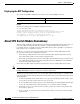
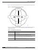
Figure 3-1 shows the valid hardware transition states for a system with redundant CPU switch modules.
Figure 3-1 CPU Switch Module State Transition Diagram
In response to redundancy events, such as switchovers and reboots of the active CPU switch module, the
software transitions through a series of software redundancy states. Table 3-2 lists some of the
significant software states.
Nonparticipant
Error
Not plugged in
(processor card
removed)
Active Standby
58645
Table 3-2 CPU Switch Module Software States
State Description
Disabled The standby CPU switch module is not yet running the system image or is in
maintenance mode.
Standby cold The standby CPU switch module is running the system image but has not
begun to synchronize data from the active CPU switch module.
Standby hot The standby CPU switch module has fully synchronized the configuration and
other data from the active CPU switch module. It will remain in the
hot-standby state until a switchover occurs.
Active The CPU switch module is in the active hardware state and has completed all
switchover or initial bootup processing. It is fully ready to control the system.