
user manual


3 Using Cisco Transport Controller 78-11719-02 July 2001
Cisco ONS 15327 User Documentation3-18
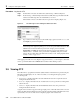
Figure 3-9 Example of a customized map graphic
Step 6
At the network view, fill the window with the desired map graphic:
(a) Click the Zoom Selected Area tool in the toolbar.
The cursor arrow becomes a crosshair.
(b) Holding down the left button on your mouse, drag the crosshair diagonally across
the area of the map that you want shown.
The view that appears becomes the default network map view for that particular log-in or user
profile.
Step 7 From the menu bar, choose Edit > Preferences.
The Preference dialog box appears.
Step 8 Click the General tab.
Step 9 Use the down arrow and up arrow buttons to enter the correct longitudes and latitudes for
the top, bottom, left, and right edges of the entire map graphic (not just the portion where
you zoomed in).
Step 10 Click Apply and click OK.
3.5.2.2 Creating Domains
You can create domains for managing the display of multiple nodes on the network-view map. You
can reduce the number of icons on the map or group nodes by location.
Procedure: Create a New Domain
Step 1 Right-click the network-view map.
Step 2 Choose Create New Domain.
Step 3 Type a name for your domain.