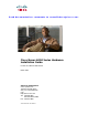
Send documentation comments to nexus5kdocs@cisco.com. Cisco Nexus 6000 Series Hardware Installation Guide For the Cisco Nexus 6004 Switch March 2013 Americas Headquarters Cisco Systems, Inc. 170 West Tasman Drive San Jose, CA 95134-1706 USA http://www.cisco.
Send documentation comments to nexus5kdocs@cisco.com. THE SPECIFICATIONS AND INFORMATION REGARDING THE PRODUCTS IN THIS MANUAL ARE SUBJECT TO CHANGE WITHOUT NOTICE. ALL STATEMENTS, INFORMATION, AND RECOMMENDATIONS IN THIS MANUAL ARE BELIEVED TO BE ACCURATE BUT ARE PRESENTED WITHOUT WARRANTY OF ANY KIND, EXPRESS OR IMPLIED. USERS MUST TAKE FULL RESPONSIBILITY FOR THEIR APPLICATION OF ANY PRODUCTS.
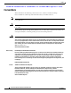
Send documentation comments to nexus5kdocs@cisco.com. Preface This preface describes the audience, organization, and conventions of the Cisco Nexus 6000 Series Hardware Installation Guide. It also provides information on how to obtain related documentation. Audience To use this installation guide, you must be familiar with electronic circuitry and wiring practices and preferably be an electronic or electromechanical technician.
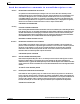
Preface Send documentation comments to nexus5kdocs@cisco.com. Conventions This document uses the following conventions for notes, cautions, and safety warnings. Notes and Cautions contain important information that you should be aware of. Note Means reader take note. Notes contain helpful suggestions or references to material that are not covered in the publication. Caution Means reader be careful. You are capable of doing something that might result in equipment damage or loss of data.
Preface Send documentation comments to nexus5kdocs@cisco.com. Attention IMPORTANTES INFORMATIONS DE SÉCURITÉ Ce symbole d'avertissement indique un danger. Vous vous trouvez dans une situation pouvant entraîner des blessures ou des dommages corporels. Avant de travailler sur un équipement, soyez conscient des dangers liés aux circuits électriques et familiarisez-vous avec les procédures couramment utilisées pour éviter les accidents.
Preface Send documentation comments to nexus5kdocs@cisco.com. ¡Advertencia! INSTRUCCIONES IMPORTANTES DE SEGURIDAD Este símbolo de aviso indica peligro. Existe riesgo para su integridad física. Antes de manipular cualquier equipo, considere los riesgos de la corriente eléctrica y familiarícese con los procedimientos estándar de prevención de accidentes.
Preface Send documentation comments to nexus5kdocs@cisco.com. Aviso INSTRUÇÕES IMPORTANTES DE SEGURANÇA Este símbolo de aviso significa perigo. Você se encontra em uma situação em que há risco de lesões corporais. Antes de trabalhar com qualquer equipamento, esteja ciente dos riscos que envolvem os circuitos elétricos e familiarize-se com as práticas padrão de prevenção de acidentes.
Preface Send documentation comments to nexus5kdocs@cisco.com.
Preface Send documentation comments to nexus5kdocs@cisco.com.
Preface Send documentation comments to nexus5kdocs@cisco.com. Related Documentation Documentation for Cisco MDS 9200 Series Switches and Cisco Nexus 2000 Series Fabric Extenders is available at the following URL: http://www.cisco.com/en/US/products/ps9670/tsd_products_support_series_home.
Send documentation comments to nexus5kdocs@cisco.com. CH A P T E R 1 Overview This chapter provides an overview of the Cisco Nexus 6000 Series switch. The overview includes information on the expansion modules, power supplies, and fan modules that you can include with the switch.
Chapter 1 Overview Cisco Nexus 6004 Switch Send documentation comments to nexus5kdocs@cisco.com. Chassis The Cisco Nexus 6004 switch chassis is 4 RU, 6.97 inches (17.7 cm) tall, 17.3 inches (43.9 cm) wide, and 30 inches (76.2 cm) deep. It is designed to be mounted in a standard 19-inch wide rack. The front of the switch, shown in Figure 1-1, has a console management port and USBport, six power supplies, and four fan modules.
Chapter 1 Overview Cisco Nexus 6004 Switch Send documentation comments to nexus5kdocs@cisco.com. Figure 1-2 Rear View of the Cisco Nexus 6004 Switch 1 Fixed ports 2 Four expansion modules 3 4RU chassis Expansion Modules Expansion modules allow the Cisco Nexus 6004 switch to be configured as cost-effective 10/40-Gigabit Ethernet switches and as I/O consolidation platforms with native Fibre Channel connectivity.
Chapter 1 Overview Cisco Nexus 6004 Switch Send documentation comments to nexus5kdocs@cisco.com. Figure 1-3 Cisco Nexus 6004 Expansion Module Ports All the individual ports on the Cisco Nexus 6004 switch are numbered and groups of ports are numbered based on their function. Depending on how it is configured, there are 96 ports on the the Cisco Nexus 6004 switch. The ports are numbered from top-to-bottom and from left-to-right.
Chapter 1 Overview Cisco Nexus 6004 Switch Send documentation comments to nexus5kdocs@cisco.com. Power Supply The Cisco Nexus 6004 switch uses a front-end power supply. The chassis has slots for six power supplies. Table 1-1 lists the power supplies that you can order with the Cisco Nexus 6004 switch.
Chapter 1 Overview Cisco Nexus 6004 Switch Send documentation comments to nexus5kdocs@cisco.com. Figure 1-6 Cisco Nexus 6004 Fan Module The bicolor status LED indicates fan tray health. Green indicates normal operation, while amber indicates a fan failure. For more information about LEDs, see Table D-1. Airflow Power supplies and fan modules should be selected depending on the desired air flow direction.
Chapter 1 Overview Cisco Nexus 6004 Switch Send documentation comments to nexus5kdocs@cisco.com. Transceivers The Cisco Nexus 6004 series switch supports a wide variety of 10 and 40 Gigabit Ethernet connectivity options using Cisco 40GBASE QSFP and breakout cable options.
Chapter 1 Overview Cisco Nexus 6004 Switch Send documentation comments to nexus5kdocs@cisco.com.
Send documentation comments to nexus5kdocs@cisco.com. CH A P T E R 2 Installing the Cisco Nexus 6000 Series Switches This chapter describes how to install the Cisco Nexus 6004 switch.
Chapter 2 Installing the Cisco Nexus 6000 Series Switches Preparing for Installation Send documentation comments to nexus5kdocs@cisco.com. Preparing for Installation This section describes how to prepare the Cisco Nexus 6004 switch for installation.
Chapter 2 Installing the Cisco Nexus 6000 Series Switches Preparing for Installation Send documentation comments to nexus5kdocs@cisco.com. • Record the information listed in Appendix G, “Site Planning and Maintenance Records,” as you install and configure the switch. • Ensure that there is adequate space around the switch to allow for servicing the switch and for adequate airflow (Appendix B, “Technical Specifications,” lists the service and airflow requirements).
Chapter 2 Installing the Cisco Nexus 6000 Series Switches Preparing for Installation Send documentation comments to nexus5kdocs@cisco.com.
Chapter 2 Installing the Cisco Nexus 6000 Series Switches Installing the Switch Send documentation comments to nexus5kdocs@cisco.com.
Chapter 2 Installing the Cisco Nexus 6000 Series Switches Installing the Switch Send documentation comments to nexus5kdocs@cisco.com. Note b. Step 2 You can align any four of the holes in the front rack-mount bracket to four of the six screw holes in the chassis. The holes that you use depend on the requirements of your rack. Repeat Step 1a with the other front rack-mount bracket on the other side of the switch. Install the rear rack-mount guides on the chassis as follows: a.
Chapter 2 Installing the Cisco Nexus 6000 Series Switches Grounding the Switch Send documentation comments to nexus5kdocs@cisco.com. Figure 2-1 Slider Rails c. Holding the chassis level, insert two screws (12-24 or 10-32, depending on the rack type) through the cage nuts and the holes in one of the front rack-mount brackets and into the threaded holes in the rack-mounting rail. d. Repeat for the other front rack-mount bracket on the other side of the switch.
Chapter 2 Installing the Cisco Nexus 6000 Series Switches Grounding the Switch Send documentation comments to nexus5kdocs@cisco.com. Proper Grounding Practices Grounding is one of the most important parts of equipment installation. Proper grounding practices ensure that the buildings and the installed equipment within them have low-impedance connections and low-voltage differentials between chassis.
Chapter 2 Installing the Cisco Nexus 6000 Series Switches Grounding the Switch Send documentation comments to nexus5kdocs@cisco.com. Table 2-2 Proper Grounding Guidelines (continued) Environment Electromagnetic Noise Severity Level Grounding Recommendations New commercial building is not Low subject to natural environmental noise or man-made industrial noise. This building contains a standard office environment.
Chapter 2 Installing the Cisco Nexus 6000 Series Switches Grounding the Switch Send documentation comments to nexus5kdocs@cisco.com. • Note If your chassis does not have the system ground attached, you must install the system ground lug. See the “Establishing the System Ground” section on page 2-11 for installation instructions and location of the chassis system ground pads.
Chapter 2 Installing the Cisco Nexus 6000 Series Switches Grounding the Switch Send documentation comments to nexus5kdocs@cisco.com. Establishing the System Ground This section describes how to connect a system ground to the Cisco Nexus 6000 Series switch. You must use the system ground on AC-powered systems if you are installing this equipment in a U.S. or European Central Office.
Chapter 2 Installing the Cisco Nexus 6000 Series Switches Starting the Switch Send documentation comments to nexus5kdocs@cisco.com. Warning When installing or replacing the unit, the ground connection must always be made first and disconnected last. Statement 1046 Caution We recommend grounding the chassis, even if the rack is already grounded. Caution All power supplies must be grounded.
Chapter 2 Installing the Cisco Nexus 6000 Series Switches Starting the Switch Send documentation comments to nexus5kdocs@cisco.com. Note Warning Do not connect the Ethernet port to the LAN until the initial switch configuration has been performed. For instructions on configuring the switch, see the Cisco Nexus 6000 Series CLI Configuration Guide. For instructions on connecting to the console port, see the “Connecting to the Console Port” section on page 3-2.
Chapter 2 Installing the Cisco Nexus 6000 Series Switches Starting the Switch Send documentation comments to nexus5kdocs@cisco.com. Note Step 9 If you purchased this product through a Cisco reseller, contact the reseller directly for technical support. If you purchased this product directly from Cisco, contact Cisco Technical Support at this URL: http://www.cisco.com/en/US/support/tsd_cisco_worldwide_contacts.html.
Send documentation comments to nexus5kdocs@cisco.com. CH A P T E R 3 Connecting the Switch This chapter describes how to connect the Cisco Nexus 6004 switche to the following types of ports: Caution • Console port —A port that you can use to create a local management connection. • Ethernet ports, both encrypted and unencrypted—These ports can be used to connect to a LAN.
Chapter 3 Connecting the Switch Preparing for Network Connections Send documentation comments to nexus5kdocs@cisco.com.
Chapter 3 Connecting the Switch Connecting to the Ethernet Connector Port Send documentation comments to nexus5kdocs@cisco.com. Connecting to the Ethernet Connector Port Caution To prevent an IP address conflict, do not connect the management port to the network until the initial configuration is complete. For configuration instructions, see the Cisco Nexus 6000 Series CLI Configuration Guide. This section describes how to connect the Ethernet connector port to an external hub, switch, or router.
Chapter 3 Connecting the Switch Connecting to an Ethernet Port Send documentation comments to nexus5kdocs@cisco.com. Step 2 Remove the dust cover from the port cage. Step 3 Remove the dust cover from the port end of the transceiver. Step 4 Insert the transceiver into the port as follows: • If the transceiver has a Mylar tab latch, position the transceiver with the tab on the bottom, and then gently insert the transceiver into the port until it clicks into place.
Chapter 3 Connecting the Switch Connecting to an Ethernet Port Send documentation comments to nexus5kdocs@cisco.com. Step 4 Insert a dust cover into the port end of the transceiver and place the transceiver on an antistatic mat or into a static shielding bag if you plan to return it to the factory. Step 5 Install a replacement transceiver (see the “Installing a Transceiver” section on page 3-3). If another transceiver is not being installed, protect the optical cage by inserting a clean cover.
Chapter 3 Connecting the Switch Connecting to an Ethernet Port Send documentation comments to nexus5kdocs@cisco.com. Caution If the cable does not remove easily, ensure that any latch present on the cable has been released before continuing. To remove the cable, follow these steps: Step 1 Attach an ESD-preventive wrist strap and follow its instructions for use.
Send documentation comments to nexus5kdocs@cisco.com. CH A P T E R 4 Replacing Components This chapter describes how to remove and install components for the Cisco Nexus 6000 Platform switch.
Chapter 4 Replacing Components Replacing LEMs Send documentation comments to nexus5kdocs@cisco.com. Step 5 With one hand on the ejector handle and front of the module, pull the module part way out of its slot in the chassis. Step 6 Place your other hand under the module to support its weight and fully remove the module. Step 7 Place the module on an antistatic surface or pack it in its packing materials.
Chapter 4 Replacing Components Replacing Modules Send documentation comments to nexus5kdocs@cisco.com. Installing a LEM To install a LEM in a Cisco Nexus 6004 chassis, follow these steps: Step 1 Insert the LEM into the slot and make sure it is firmly installed. Step 2 The LEM will auto power on if the poweroff command was not executed earlier on this slot. Otherwise no poweroff module will power it on.
Chapter 4 Replacing Components Replacing or Installing Power Supplies Send documentation comments to nexus5kdocs@cisco.com. Replacing or Installing Power Supplies The Cisco Nexus 6000 series support six power supplies, but may be used with three power supplies. You must fill the unused power supply slots with a blank modules to maintain the designed airflow. If you need to replace an existing power supply, follow the procedures that explain how to remove and install power supplies.
Chapter 4 Replacing Components Replacing or Installing Power Supplies Send documentation comments to nexus5kdocs@cisco.com. Step 1 Ensure that the system (earth) ground connection has been made. For ground connection instructions, see the “Grounding the Switch” section on page 2-7. Step 2 If the power supply bay has a filler panel, press the latches on the sides of the filler panel, and then slide it out of the power supply bay.
Chapter 4 Replacing Components Replacing or Installing Power Supplies Send documentation comments to nexus5kdocs@cisco.com. Before installing a DC power supply to the switch, you will need to attach DC connection wires that you provide (10 GA recommended) to the DC power connector included in the DC power supply’s accessory kit. To wire the connector: Step 1 Using a 1/8” flat head screwdriver or No. 1 Phillips head screwdriver, loosen the set screws on the connector to freely accept the power wires.
Chapter 4 Replacing Components Replacing a Fan Module Send documentation comments to nexus5kdocs@cisco.com. Replacing a Fan Module The fan module is designed to be removed and replaced while the system is operating without presenting an electrical hazard or damage to the system, if the replacement is performed promptly. Note The airflow direction must be the same for all power suply and fan modules in the chassis.
Chapter 4 Replacing Components Removing the Cisco Nexus 6000 Platform Chassis Send documentation comments to nexus5kdocs@cisco.com. Note If you purchased this product through a Cisco reseller, contact the reseller directly for technical support. If you purchased this product directly from Cisco, contact Cisco Technical Support at this URL: http://www.cisco.com/en/US/support/tsd_cisco_worldwide_contacts.html.
Send documentation comments to nexus5kdocs@cisco.com.
Appendix A Cabinet and Rack Installation Cable Management Guidelines Send documentation comments to nexus5kdocs@cisco.com. • The width between the rack-mounting rails must be at least 19 inches if the rear of the switch is not attached to the rack. For four-post EIA racks, this is the distance between the two front rails.
Send documentation comments to nexus5kdocs@cisco.com. A P P E N D I X B Technical Specifications This appendix describes the technical specifications for the Cisco Nexus 6004 switch. This appendix includes the following sections: Note • Switch Specifications, page B-1 • Environmental Specifications, page B-1 • Expansion Module Specifications, page B-2 • Power Specifications, page B-2 Specifications for cables and connectors are provided in Appendix C, “Cable and Port Specifications.
Appendix B Technical Specifications Expansion Module Specifications Send documentation comments to nexus5kdocs@cisco.com.
Appendix B Technical Specifications Send documentation comments to nexus5kdocs@cisco.com.
Appendix B Technical Specifications Send documentation comments to nexus5kdocs@cisco.com.
Send documentation comments to nexus5kdocs@cisco.com. A P P E N D I X C Cable and Port Specifications This appendix provides cable and port specifications for the Cisco Nexus 6004 switch. This appendix includes the following sections: • Console Port, page C-2 • Supported Power Cords and Plugs, page C-2 • Jumper Power Cord, page C-8 Cable RJ-45 Connector Pinouts Table C-1 lists the pinouts for the RJ-45 connector on the console cable.
Appendix C Cable and Port Specifications Console Port Send documentation comments to nexus5kdocs@cisco.com. Console Port The console port is an asynchronous RS-232 serial port with an RJ-45 connector. Supported Power Cords and Plugs Each power supply has a separate power cord. Standard power cords or jumper power cords are available for connection to a power distribution unit that has IEC 60320 C19 outlet receptacles.
Appendix C Cable and Port Specifications Supported Power Cords and Plugs Send documentation comments to nexus5kdocs@cisco.com. Table C-2 Power Cords for the Cisco Nexus 6004 Switch (continued) Length Description Feet Meters Power Cord Reference Illustration CAB-9K10A-UK Power cord 250 VAC 10 A, BS1363 plug (13 A fuse) United Kingdom 8.2 2.5 Figure C-9 CAB-AC-250V/13A Power cord 250 VAC 13 A, NEMA L6-20 plug North America 6.6 2.
Appendix C Cable and Port Specifications Supported Power Cords and Plugs Send documentation comments to nexus5kdocs@cisco.com. Figure C-2 CAB-9K10A-AU Connector: EL 701C (IEC 60320/C15) Plug: EL 206 A.S. 3112-2000) SFS-250V-10A-CN Plug: EL 218 (CCEE GB2009) Cordset rating 10A, 250V (2500 mm) Connector: EL 701 (IEC60320/C13) CAB-9K10A-EU Plug: M2511 Cordset rating: 10A/16 A, 250 V Length: 8 ft 2 in. (2.
Appendix C Cable and Port Specifications Supported Power Cords and Plugs Send documentation comments to nexus5kdocs@cisco.com. Figure C-5 SFS-250V-10A-ID OVE Cordset rating 16A, 250V (2500mm) Plug: EL 208 187490 Connector: EL 701 Figure C-6 SFS-250V-10A-IS EL-212 16A 250V Cordset rating 10A, 250V/500V MAX (2500 mm) Connector: EL 701B (IEC60320/C13) Figure C-7 186574 Plug: EL 212 (SI-32) CAB-9K10A-IT Cordset rating: 10 A, 250 V Length: 8 ft 2 in. (2.
Appendix C Cable and Port Specifications Supported Power Cords and Plugs Send documentation comments to nexus5kdocs@cisco.com.
Appendix C Cable and Port Specifications Supported Power Cords and Plugs Send documentation comments to nexus5kdocs@cisco.com. CAB-N5K6A-NA Plug: NEMA 6-15P Cordset rating: 10 A, 250 V Length: 8.2 ft Connector: IEC60320/C13 Figure C-12 186570 Figure C-11 CAB-9K12A-NA Connector: IEC60320/C15 Plug: NEMA 5-15P Figure C-13 192260 Cordset rating 13A, 125V (8.2 feet) (2.
Appendix C Cable and Port Specifications Jumper Power Cord Send documentation comments to nexus5kdocs@cisco.com. Figure C-14 CAB-IND-10A Connector EL701B (IEC60320/C13) Plug: EL 208B (IS 6538-1971) 192259 Cordset rating 10A, 250V (8.2 feet) (2.5m) Jumper Power Cord Figure C-15 shows the plug connector on the optional jumper power cord for the Cisco Nexus 6000 Series switches. This cable plugs into the power supply, and the receptacle of a power distribution unit for a cabinet.
Send documentation comments to nexus5kdocs@cisco.com. A P P E N D I X D LEDs This appendix describes the conditions indicated by the chassis and module LEDs on the Cisco Nexus 6000 Series switches.
Appendix D LEDs Port LEDs Send documentation comments to nexus5kdocs@cisco.com. Indicator Location Function Color Status State PSU Status Indicators Power Supply (front) PSU Health (multi-color) Green Off No AC power to power supply Solid On Power supply on and OK Solid On Power supply failures, over voltage, over current, over temperature 1 Hz AC present, 3.
Appendix D LEDs Port LEDs Send documentation comments to nexus5kdocs@cisco.com. Ethernet Port LEDs Table D-2 lists the LED descriptions for the RJ-45 Ethernet port LEDs. Table D-2 Ethernet Port LED Descriptions LED Status Description Left Off No link Solid green Physical link Off No activity Blinking green Activity Right Ethernet and Fibre Channel LEDs There are activity LED’s per-port on the Cisco Nexus 6004 faceplate.
Appendix D LEDs Port LEDs Send documentation comments to nexus5kdocs@cisco.com.
Send documentation comments to nexus5kdocs@cisco.com. A P P E N D I X E Troubleshooting Hardware Components This appendix describes how to identify and resolve problems that might occur with the hardware components of a Cisco Nexus 6000 Series switch.
Appendix E Troubleshooting Hardware Components Power Supply Conditions Send documentation comments to nexus5kdocs@cisco.com. Installation Best Practices When installing the switch, follow these best practices: • Plan your site configuration and prepare the site before installing the chassis. • Verify that you have the appropriate power supplies for your chassis configuration. • Install the chassis following the rack and airflow guidelines presented in this guide.
Appendix E Troubleshooting Hardware Components Power Supply Conditions Send documentation comments to nexus5kdocs@cisco.com.
Appendix E Troubleshooting Hardware Components Power Supply Conditions Send documentation comments to nexus5kdocs@cisco.com.
Send documentation comments to nexus5kdocs@cisco.com. A P P E N D I X F Accessory Kits This appendix describes the contents of the accessory kits for the Cisco Nexus 6000 Series switches.
Appendix F Accessory Kits Cisco Nexus 6004 Switch Accessory Kit Send documentation comments to nexus5kdocs@cisco.com.
Send documentation comments to nexus5kdocs@cisco.com. A P P E N D I X G Site Planning and Maintenance Records This appendix provides log sheets that you can use to record information when installing a Cisco Nexus 6000 Series switch.
Appendix G Site Planning and Maintenance Records Site Preparation Checklist Send documentation comments to nexus5kdocs@cisco.com. Table G-1 Site Planning Checklist Task No.
Appendix G Site Planning and Maintenance Records Contact and Site Information Send documentation comments to nexus5kdocs@cisco.com. 3. EMI = electromagnetic interference. 4. RFI = radio frequency interference. Contact and Site Information Use the following worksheet (Table G-2) to record contact and site information.
Appendix G Site Planning and Maintenance Records Chassis and Module Information Send documentation comments to nexus5kdocs@cisco.com. Chassis and Module Information Use the following worksheets (Table G-3 and Table G-4) to record information about the chassis and modules.