
- Cisco Nexus 6000 Series Installation Guide
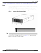
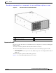
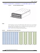

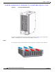

Table Of Contents
- Preface
- Overview
- Installing the Cisco Nexus 6000 Series Switches
- Connecting the Switch
- Replacing Components
- Cabinet and Rack Installation
- Technical Specifications
- Cable and Port Specifications
- LEDs
- Troubleshooting Hardware Components
- Accessory Kits
- Site Planning and Maintenance Records
Send documentation comments to nexus5kdocs@cisco.com.
1-2
Cisco Nexus 6000 Series Hardware Installation Guide
OL-15902-01
Chapter 1 Overview
Cisco Nexus 6004 Switch
Chassis
The Cisco Nexus 6004 switch chassis is 4 RU, 6.97 inches (17.7 cm) tall, 17.3 inches (43.9 cm) wide,
and 30 inches (76.2 cm) deep.
It is designed to be mounted in a standard 19-inch wide rack. The front of the switch, shown in
Figure 1-1, has a console management port and USBport, six power supplies, and four fan modules.
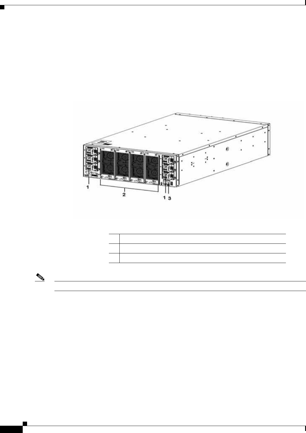
Figure 1-1 Front View of the Cisco Nexus 6004 switch
Note The fans and power supplies need to be configured.
The rear of the Cisco Nexus 6004 switch chassis, shown in Figure 1-2, has 48fixed 10/40-Gigabit
Ethernet ports, and four slots for expansion modules.
1 Six power supplies with 3+3 grid redundancy
2 Four fan module with 3+1 redundancy
3 Console Mgmt0 port and USBport