
user manual


Table Of Contents
- Cisco Nexus 3000 NX-OS Layer 2 Switching Configuration Guide, Release 5.0(3)U3(1)
- Contents
- Preface
- New and Changed Information for this Release
- Overview
- Configuring Ethernet Interfaces
- Information About Ethernet Interfaces
- Configuring Ethernet Interfaces
- Configuring the UDLD Mode
- Changing an Interface Port Mode
- Configuring Interface Speed
- Disabling Link Negotiation
- Configuring the CDP Characteristics
- Enabling or Disabling CDP
- Enabling the Error-Disabled Detection
- Enabling the Error-Disabled Recovery
- Configuring the Error-Disabled Recovery Interval
- Configuring the Debounce Timer
- Configuring the Description Parameter
- Disabling and Restarting Ethernet Interfaces
- Displaying Interface Information
- Displaying Input Packet Discard Information
- Default Physical Ethernet Settings
- Configuring VLANs
- Configuring Private VLANs
- Information About Private VLANs
- Guidelines and Limitations for Private VLANs
- Configuring a Private VLAN
- Enabling Private VLANs
- Configuring a VLAN as a Private VLAN
- Associating Secondary VLANs with a Primary Private VLAN
- Configuring an Interface as a Private VLAN Host Port
- Configuring an Interface as a Private VLAN Promiscuous Port
- Configuring a Promiscuous Trunk Port
- Configuring an Isolated Trunk Port
- Configuring the Allowed VLANs for PVLAN Trunking Ports
- Configuring Native 802.1Q VLANs on Private VLANs
- Verifying the Private VLAN Configuration
- Configuring Access and Trunk Interfaces
- Configuring Switching Modes
- Configuring Rapid PVST+
- Information About Rapid PVST+
- Understanding STP
- Understanding Rapid PVST+
- Rapid PVST+ and IEEE 802.1Q Trunks
- Rapid PVST+ Interoperation with Legacy 802.1D STP
- Rapid PVST+ Interoperation with 802.1s MST
- Configuring Rapid PVST+
- Enabling Rapid PVST+
- Enabling Rapid PVST+ per VLAN
- Configuring the Root Bridge ID
- Configuring a Secondary Root Bridge
- Configuring the Rapid PVST+ Port Priority
- Configuring the Rapid PVST+ Pathcost Method and Port Cost
- Configuring the Rapid PVST+ Bridge Priority of a VLAN
- Configuring the Rapid PVST+ Hello Time for a VLAN
- Configuring the Rapid PVST+ Forward Delay Time for a VLAN
- Configuring the Rapid PVST+ Maximum Age Time for a VLAN
- Specifying the Link Type
- Restarting the Protocol
- Verifying Rapid PVST+ Configurations
- Information About Rapid PVST+
- Configuring Multiple Spanning Tree
- Information About MST
- Configuring MST
- MST Configuration Guidelines
- Enabling MST
- Entering MST Configuration Mode
- Specifying the MST Name
- Specifying the MST Configuration Revision Number
- Specifying the Configuration on an MST Region
- Mapping and Unmapping VLANs to MST Instances
- Mapping Secondary VLANs to Same MSTI as Primary VLANs for Private VLANs
- Configuring the Root Bridge
- Configuring a Secondary Root Bridge
- Configuring the Port Priority
- Configuring the Port Cost
- Configuring the Switch Priority
- Configuring the Hello Time
- Configuring the Forwarding-Delay Time
- Configuring the Maximum-Aging Time
- Configuring the Maximum-Hop Count
- Configuring PVST Simulation Globally
- Configuring PVST Simulation Per Port
- Specifying the Link Type
- Restarting the Protocol
- Verifying MST Configurations
- Configuring STP Extensions
- About STP Extensions
- Information About STP Extensions
- Configuring STP Extensions
- STP Extensions Configuration Guidelines
- Configuring Spanning Tree Port Types Globally
- Configuring Spanning Tree Edge Ports on Specified Interfaces
- Configuring Spanning Tree Network Ports on Specified Interfaces
- Enabling BPDU Guard Globally
- Enabling BPDU Guard on Specified Interfaces
- Enabling BPDU Filtering Globally
- Enabling BPDU Filtering on Specified Interfaces
- Enabling Loop Guard Globally
- Enabling Loop Guard or Root Guard on Specified Interfaces
- Verifying STP Extension Configuration
- About STP Extensions
- Configuring LLDP
- Configuring the MAC Address Table
- Configuring IGMP Snooping
- Configuring Traffic Storm Control
- INDEX
Election of the Root Bridge
For each VLAN, the switch with the lowest numerical value of the bridge ID is elected as the root bridge. If
all switches are configured with the default priority (32768), the switch with the lowest MAC address in the
VLAN becomes the root bridge. The bridge priority value occupies the most significant bits of the bridge ID.
When you change the bridge priority value, you change the probability that the switch will be elected as the
root bridge. Configuring a lower value increases the probability; a higher value decreases the probability.
The STP root bridge is the logical center of each spanning tree topology in a network. All paths that are not
needed to reach the root bridge from anywhere in the network are placed in STP blocking mode.
BPDUs contain information about the transmitting bridge and its ports, including bridge and MAC addresses,
bridge priority, port priority, and path cost. STP uses this information to elect the root bridge for the STP
instance, to elect the root port leading to the root bridge, and to determine the designated port for each segment.
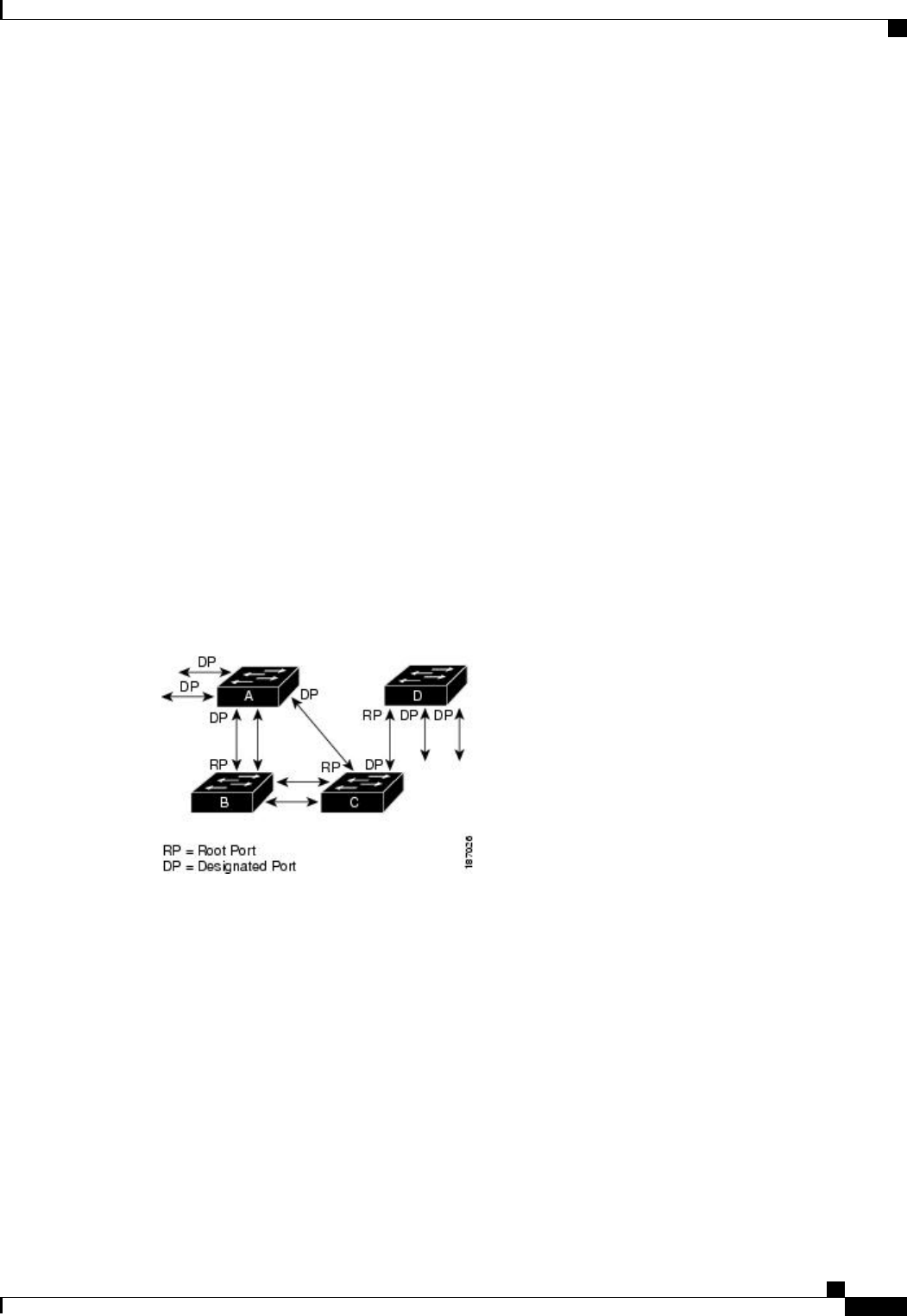
Creating the Spanning Tree Topology
In the following figure, Switch A is elected as the root bridge because the bridge priority of all the switches
is set to the default (32768) and Switch A has the lowest MAC address. However, due to traffic patterns,
number of forwarding ports, or link types, Switch A might not be the ideal root bridge. By increasing the
priority (lowering the numerical value) of the ideal switch so that it becomes the root bridge, you force an
STP recalculation to form a new spanning tree topology with the ideal switch as the root.
Figure 8: Spanning Tree Topology
When the spanning tree topology is calculated based on default parameters, the path between source and
destination end stations in a switched network might not be ideal. For instance, connecting higher-speed links
to a port that has a higher number than the current root port can cause a root-port change. The goal is to make
the fastest link the root port.
For example, assume that one port on Switch B is a fiber-optic link, and another port on Switch B (an unshielded
twisted-pair [UTP] link) is the root port. Network traffic might be more efficient over the high-speed fiber-optic
link. By changing the STP port priority on the fiber-optic port to a higher priority (lower numerical value)
than the root port, the fiber-optic port becomes the new root port.
Cisco Nexus 3000 NX-OS Layer 2 Switching Configuration Guide, Release 5.0(3)U3(1)
OL-26590-01 67
Configuring Rapid PVST+
Understanding STP