
user manual


Table Of Contents
- Cisco Nexus 3000 NX-OS Layer 2 Switching Configuration Guide, Release 5.0(3)U3(1)
- Contents
- Preface
- New and Changed Information for this Release
- Overview
- Configuring Ethernet Interfaces
- Information About Ethernet Interfaces
- Configuring Ethernet Interfaces
- Configuring the UDLD Mode
- Changing an Interface Port Mode
- Configuring Interface Speed
- Disabling Link Negotiation
- Configuring the CDP Characteristics
- Enabling or Disabling CDP
- Enabling the Error-Disabled Detection
- Enabling the Error-Disabled Recovery
- Configuring the Error-Disabled Recovery Interval
- Configuring the Debounce Timer
- Configuring the Description Parameter
- Disabling and Restarting Ethernet Interfaces
- Displaying Interface Information
- Displaying Input Packet Discard Information
- Default Physical Ethernet Settings
- Configuring VLANs
- Configuring Private VLANs
- Information About Private VLANs
- Guidelines and Limitations for Private VLANs
- Configuring a Private VLAN
- Enabling Private VLANs
- Configuring a VLAN as a Private VLAN
- Associating Secondary VLANs with a Primary Private VLAN
- Configuring an Interface as a Private VLAN Host Port
- Configuring an Interface as a Private VLAN Promiscuous Port
- Configuring a Promiscuous Trunk Port
- Configuring an Isolated Trunk Port
- Configuring the Allowed VLANs for PVLAN Trunking Ports
- Configuring Native 802.1Q VLANs on Private VLANs
- Verifying the Private VLAN Configuration
- Configuring Access and Trunk Interfaces
- Configuring Switching Modes
- Configuring Rapid PVST+
- Information About Rapid PVST+
- Understanding STP
- Understanding Rapid PVST+
- Rapid PVST+ and IEEE 802.1Q Trunks
- Rapid PVST+ Interoperation with Legacy 802.1D STP
- Rapid PVST+ Interoperation with 802.1s MST
- Configuring Rapid PVST+
- Enabling Rapid PVST+
- Enabling Rapid PVST+ per VLAN
- Configuring the Root Bridge ID
- Configuring a Secondary Root Bridge
- Configuring the Rapid PVST+ Port Priority
- Configuring the Rapid PVST+ Pathcost Method and Port Cost
- Configuring the Rapid PVST+ Bridge Priority of a VLAN
- Configuring the Rapid PVST+ Hello Time for a VLAN
- Configuring the Rapid PVST+ Forward Delay Time for a VLAN
- Configuring the Rapid PVST+ Maximum Age Time for a VLAN
- Specifying the Link Type
- Restarting the Protocol
- Verifying Rapid PVST+ Configurations
- Information About Rapid PVST+
- Configuring Multiple Spanning Tree
- Information About MST
- Configuring MST
- MST Configuration Guidelines
- Enabling MST
- Entering MST Configuration Mode
- Specifying the MST Name
- Specifying the MST Configuration Revision Number
- Specifying the Configuration on an MST Region
- Mapping and Unmapping VLANs to MST Instances
- Mapping Secondary VLANs to Same MSTI as Primary VLANs for Private VLANs
- Configuring the Root Bridge
- Configuring a Secondary Root Bridge
- Configuring the Port Priority
- Configuring the Port Cost
- Configuring the Switch Priority
- Configuring the Hello Time
- Configuring the Forwarding-Delay Time
- Configuring the Maximum-Aging Time
- Configuring the Maximum-Hop Count
- Configuring PVST Simulation Globally
- Configuring PVST Simulation Per Port
- Specifying the Link Type
- Restarting the Protocol
- Verifying MST Configurations
- Configuring STP Extensions
- About STP Extensions
- Information About STP Extensions
- Configuring STP Extensions
- STP Extensions Configuration Guidelines
- Configuring Spanning Tree Port Types Globally
- Configuring Spanning Tree Edge Ports on Specified Interfaces
- Configuring Spanning Tree Network Ports on Specified Interfaces
- Enabling BPDU Guard Globally
- Enabling BPDU Guard on Specified Interfaces
- Enabling BPDU Filtering Globally
- Enabling BPDU Filtering on Specified Interfaces
- Enabling Loop Guard Globally
- Enabling Loop Guard or Root Guard on Specified Interfaces
- Verifying STP Extension Configuration
- About STP Extensions
- Configuring LLDP
- Configuring the MAC Address Table
- Configuring IGMP Snooping
- Configuring Traffic Storm Control
- INDEX
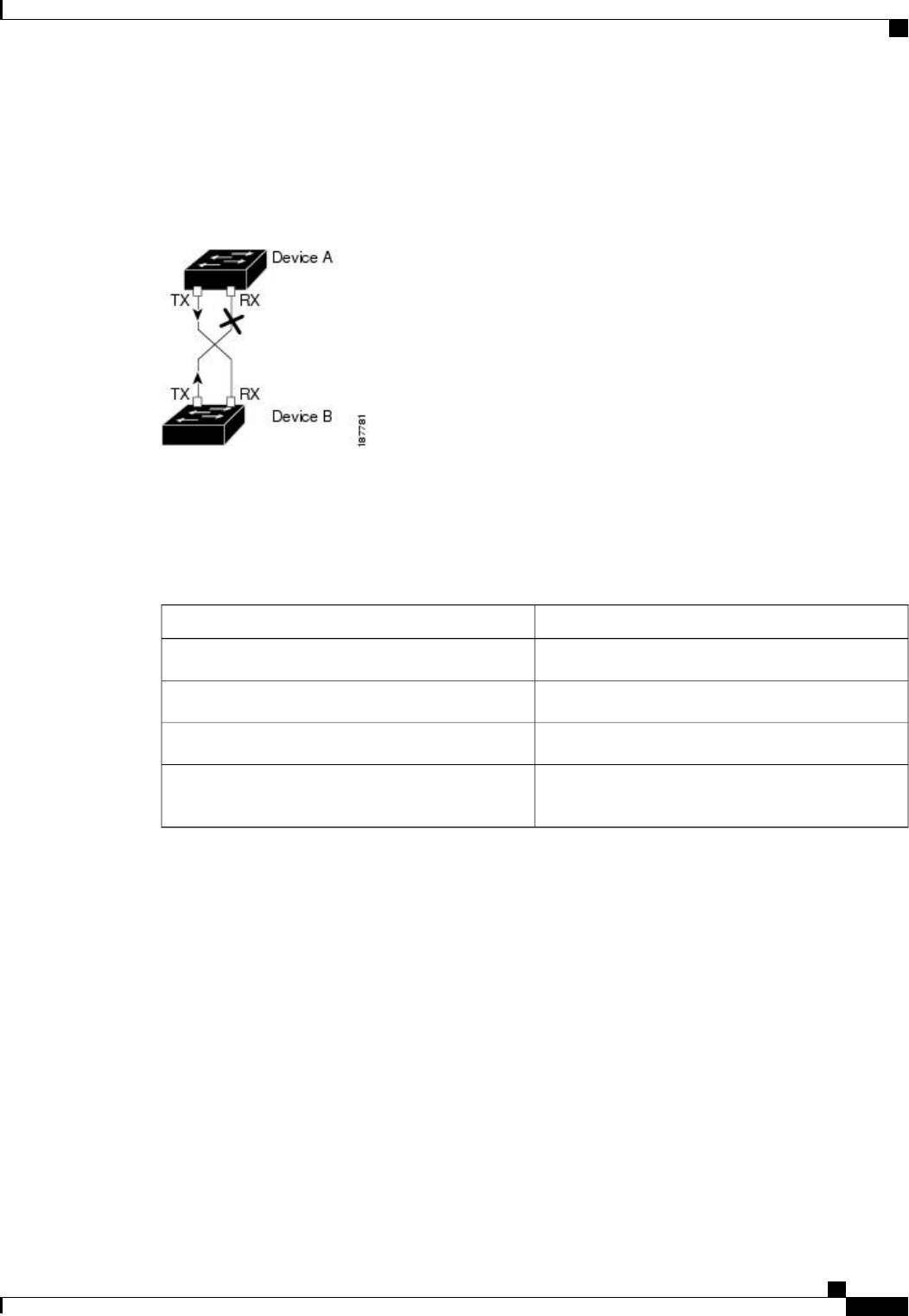
The following figure shows an example of a unidirectional link condition. Device B successfully receives
traffic from Device A on the port. However, Device A does not receive traffic from Device B on the same
port. UDLD detects the problem and disables the port.
Figure 1: Unidirectional Link
Default UDLD Configuration
The following table shows the default UDLD configuration.
Table 2: UDLD Default Configuration
Default ValueFeature
Globally disabledUDLD global enable state
DisabledUDLD aggressive mode
Enabled on all Ethernet fiber-optic LAN portsUDLD per-port enable state for fiber-optic media
Disabled on all Ethernet 10/100 and 1000BASE-TX
LAN ports
UDLD per-port enable state for twisted-pair (copper)
media
UDLD Aggressive and Nonaggressive Modes
UDLD aggressive mode is disabled by default. You can configure UDLD aggressive mode only on
point-to-point links between network devices that support UDLD aggressive mode. If UDLD aggressive mode
is enabled, when a port on a bidirectional link that has a UDLD neighbor relationship established stops
receiving UDLD frames, UDLD tries to reestablish the connection with the neighbor. After eight failed retries,
the port is disabled.
To prevent spanning tree loops, nonaggressive UDLD with the default interval of 15 seconds is fast enough
to shut down a unidirectional link before a blocking port transitions to the forwarding state (with default
spanning tree parameters).
When you enable the UDLD aggressive mode, the following occurs:
•
One side of a link has a port stuck (both transmission and receive)
•
One side of a link remains up while the other side of the link is down
Cisco Nexus 3000 NX-OS Layer 2 Switching Configuration Guide, Release 5.0(3)U3(1)
OL-26590-01 9
Configuring Ethernet Interfaces
About the Unidirectional Link Detection Parameter