
user manual


Table Of Contents
- Cisco Nexus 3000 NX-OS Layer 2 Switching Configuration Guide, Release 5.0(3)U3(1)
- Contents
- Preface
- New and Changed Information for this Release
- Overview
- Configuring Ethernet Interfaces
- Information About Ethernet Interfaces
- Configuring Ethernet Interfaces
- Configuring the UDLD Mode
- Changing an Interface Port Mode
- Configuring Interface Speed
- Disabling Link Negotiation
- Configuring the CDP Characteristics
- Enabling or Disabling CDP
- Enabling the Error-Disabled Detection
- Enabling the Error-Disabled Recovery
- Configuring the Error-Disabled Recovery Interval
- Configuring the Debounce Timer
- Configuring the Description Parameter
- Disabling and Restarting Ethernet Interfaces
- Displaying Interface Information
- Displaying Input Packet Discard Information
- Default Physical Ethernet Settings
- Configuring VLANs
- Configuring Private VLANs
- Information About Private VLANs
- Guidelines and Limitations for Private VLANs
- Configuring a Private VLAN
- Enabling Private VLANs
- Configuring a VLAN as a Private VLAN
- Associating Secondary VLANs with a Primary Private VLAN
- Configuring an Interface as a Private VLAN Host Port
- Configuring an Interface as a Private VLAN Promiscuous Port
- Configuring a Promiscuous Trunk Port
- Configuring an Isolated Trunk Port
- Configuring the Allowed VLANs for PVLAN Trunking Ports
- Configuring Native 802.1Q VLANs on Private VLANs
- Verifying the Private VLAN Configuration
- Configuring Access and Trunk Interfaces
- Configuring Switching Modes
- Configuring Rapid PVST+
- Information About Rapid PVST+
- Understanding STP
- Understanding Rapid PVST+
- Rapid PVST+ and IEEE 802.1Q Trunks
- Rapid PVST+ Interoperation with Legacy 802.1D STP
- Rapid PVST+ Interoperation with 802.1s MST
- Configuring Rapid PVST+
- Enabling Rapid PVST+
- Enabling Rapid PVST+ per VLAN
- Configuring the Root Bridge ID
- Configuring a Secondary Root Bridge
- Configuring the Rapid PVST+ Port Priority
- Configuring the Rapid PVST+ Pathcost Method and Port Cost
- Configuring the Rapid PVST+ Bridge Priority of a VLAN
- Configuring the Rapid PVST+ Hello Time for a VLAN
- Configuring the Rapid PVST+ Forward Delay Time for a VLAN
- Configuring the Rapid PVST+ Maximum Age Time for a VLAN
- Specifying the Link Type
- Restarting the Protocol
- Verifying Rapid PVST+ Configurations
- Information About Rapid PVST+
- Configuring Multiple Spanning Tree
- Information About MST
- Configuring MST
- MST Configuration Guidelines
- Enabling MST
- Entering MST Configuration Mode
- Specifying the MST Name
- Specifying the MST Configuration Revision Number
- Specifying the Configuration on an MST Region
- Mapping and Unmapping VLANs to MST Instances
- Mapping Secondary VLANs to Same MSTI as Primary VLANs for Private VLANs
- Configuring the Root Bridge
- Configuring a Secondary Root Bridge
- Configuring the Port Priority
- Configuring the Port Cost
- Configuring the Switch Priority
- Configuring the Hello Time
- Configuring the Forwarding-Delay Time
- Configuring the Maximum-Aging Time
- Configuring the Maximum-Hop Count
- Configuring PVST Simulation Globally
- Configuring PVST Simulation Per Port
- Specifying the Link Type
- Restarting the Protocol
- Verifying MST Configurations
- Configuring STP Extensions
- About STP Extensions
- Information About STP Extensions
- Configuring STP Extensions
- STP Extensions Configuration Guidelines
- Configuring Spanning Tree Port Types Globally
- Configuring Spanning Tree Edge Ports on Specified Interfaces
- Configuring Spanning Tree Network Ports on Specified Interfaces
- Enabling BPDU Guard Globally
- Enabling BPDU Guard on Specified Interfaces
- Enabling BPDU Filtering Globally
- Enabling BPDU Filtering on Specified Interfaces
- Enabling Loop Guard Globally
- Enabling Loop Guard or Root Guard on Specified Interfaces
- Verifying STP Extension Configuration
- About STP Extensions
- Configuring LLDP
- Configuring the MAC Address Table
- Configuring IGMP Snooping
- Configuring Traffic Storm Control
- INDEX
You must enable MST; Rapid PVST+ is the default spanning tree mode.Note
MST Regions
To allow switches to participate in MST instances, you must consistently configure the switches with the
same MST configuration information.
A collection of interconnected switches that have the same MST configuration is an MST region. An MST
region is a linked group of MST bridges with the same MST configuration.
The MST configuration controls the MST region to which each switch belongs. The configuration includes
the name of the region, the revision number, and the MST VLAN-to-instance assignment map.
A region can have one or multiple members with the same MST configuration. Each member must be capable
of processing 802.1w bridge protocol data units (BPDUs). There is no limit to the number of MST regions in
a network.
Each region can support up to 65 MST instances (MSTIs). Instances are identified by any number in the range
from 1 to 4094. The system reserves Instance 0 for a special instance, which is the IST. You can assign a
VLAN to only one MST instance at a time.
The MST region appears as a single bridge to adjacent MST regions and to other Rapid PVST+ regions and
802.1D spanning tree protocols.
We recommend that you do not partition the network into a large number of regions.Note
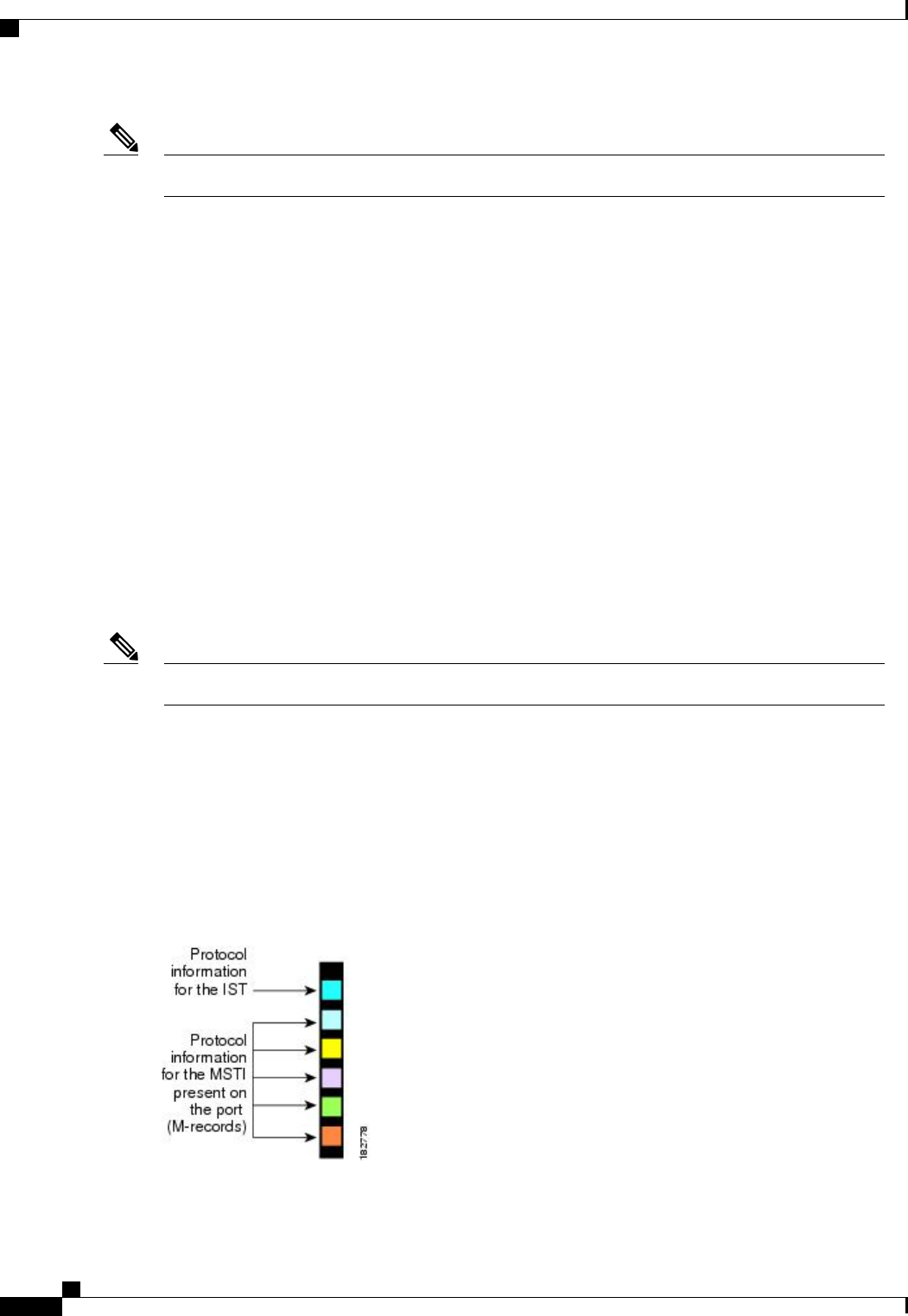
MST BPDUs
Each region has only one MST BPDU, and that BPDU carries an M-record for each MSTI within the region
(see the following figure). Only the IST sends BPDUs for the MST region; all M-records are encapsulated in
that one BPDU that the IST sends. Because the MST BPDU carries information for all instances, the number
of BPDUs that need to be processed to support MSTIs is significantly reduced.
Figure 14: MST BPDU with M-Records for MSTIs
Cisco Nexus 3000 NX-OS Layer 2 Switching Configuration Guide, Release 5.0(3)U3(1)
90 OL-26590-01
Configuring Multiple Spanning Tree
MST Regions