S e n d d o c u m e n t c o m m e n t s t o n ex u s 3 k - d o c f e e d b a ck @ c i s c o . c o m Cisco Nexus 3000 Series Hardware Installation Guide December, 2013 Americas Headquarters Cisco Systems, Inc. 170 West Tasman Drive San Jose, CA 95134-1706 USA http://www.cisco.
S e n d d o c u m e n t c o m m e n t s t o n ex u s 3 k - d o c f e e d b a ck @ c i s c o . c o m THE SPECIFICATIONS AND INFORMATION REGARDING THE PRODUCTS IN THIS MANUAL ARE SUBJECT TO CHANGE WITHOUT NOTICE. ALL STATEMENTS, INFORMATION, AND RECOMMENDATIONS IN THIS MANUAL ARE BELIEVED TO BE ACCURATE BUT ARE PRESENTED WITHOUT WARRANTY OF ANY KIND, EXPRESS OR IMPLIED. USERS MUST TAKE FULL RESPONSIBILITY FOR THEIR APPLICATION OF ANY PRODUCTS.
Se n d d o c u m e n t c o m m e n t s t o n ex u s 3 k - d o c f e e d b a ck @ c i s c o .
Contents S e n d d o c u m e n t c o m m e n t s t o n ex u s 3 k - d o c f e e d b a ck @ c i s c o .
Contents Se n d d o c u m e n t c o m m e n t s t o n ex u s 3 k - d o c f e e d b a ck @ c i s c o .
Contents S e n d d o c u m e n t c o m m e n t s t o n ex u s 3 k - d o c f e e d b a ck @ c i s c o .
Se n d d o c u m e n t c o m m e n t s t o n ex u s 3 k - d o c f e e d b a ck @ c i s c o . c o m Preface This preface describes the audience, organization, and conventions of the Cisco Nexus 3000 Series Hardware Installation Guide. It also provides information on how to obtain related documentation. Audience To use this installation guide, you must be familiar with electronic circuitry and wiring practices and preferably be an electronic or electromechanical technician.
Preface S e n d d o c u m e n t c o m m e n t s t o n ex u s 3 k - d o c f e e d b a ck @ c i s c o . c o m Conventions This document uses the following conventions for notes, cautions, and safety warnings. Notes and Cautions contain important information that you should be aware of. Note Means reader take note. Notes contain helpful suggestions or references to material that are not covered in the publication. Caution Means reader be careful.
Preface Se n d d o c u m e n t c o m m e n t s t o n ex u s 3 k - d o c f e e d b a ck @ c i s c o . c o m Attention IMPORTANTES INFORMATIONS DE SÉCURITÉ Ce symbole d'avertissement indique un danger. Vous vous trouvez dans une situation pouvant entraîner des blessures ou des dommages corporels. Avant de travailler sur un équipement, soyez conscient des dangers liés aux circuits électriques et familiarisez-vous avec les procédures couramment utilisées pour éviter les accidents.
Preface S e n d d o c u m e n t c o m m e n t s t o n ex u s 3 k - d o c f e e d b a ck @ c i s c o . c o m ¡Advertencia! INSTRUCCIONES IMPORTANTES DE SEGURIDAD Este símbolo de aviso indica peligro. Existe riesgo para su integridad física. Antes de manipular cualquier equipo, considere los riesgos de la corriente eléctrica y familiarícese con los procedimientos estándar de prevención de accidentes.
Preface Se n d d o c u m e n t c o m m e n t s t o n ex u s 3 k - d o c f e e d b a ck @ c i s c o . c o m Aviso INSTRUÇÕES IMPORTANTES DE SEGURANÇA Este símbolo de aviso significa perigo. Você se encontra em uma situação em que há risco de lesões corporais. Antes de trabalhar com qualquer equipamento, esteja ciente dos riscos que envolvem os circuitos elétricos e familiarize-se com as práticas padrão de prevenção de acidentes.
Preface S e n d d o c u m e n t c o m m e n t s t o n ex u s 3 k - d o c f e e d b a ck @ c i s c o .
Preface Se n d d o c u m e n t c o m m e n t s t o n ex u s 3 k - d o c f e e d b a ck @ c i s c o . c o m Related Documentation Documentation for the Cisco Nexus 3000 Series Switch is available at the following URL: http://www.cisco.com/en/US/products/ps11541/tsd_products_support_series_home.
Preface S e n d d o c u m e n t c o m m e n t s t o n ex u s 3 k - d o c f e e d b a ck @ c i s c o . c o m Release Notes Cisco Nexus 3000 Series Release Notes for Cisco NX-OS Release 5.0(3)U2(1) Configuration Guides Cisco Nexus 3000 Series Configuration Limits for Cisco NX-OS Release 5.0(3)U2(1) Cisco Nexus 3000 Series NX-OS Layer 2 Switching Configuration Guide, Release 5.0(3)U2(2) Cisco Nexus 3000 Series NX-OS Multicast Routing Configuration Guide, Release 5.
Preface Se n d d o c u m e n t c o m m e n t s t o n ex u s 3 k - d o c f e e d b a ck @ c i s c o . c o m Obtaining Documentation and Submitting a Service Request For information on obtaining documentation, submitting a service request, and gathering additional information, see the monthly What’s New in Cisco Product Documentation, which also lists all new and revised Cisco technical documentation, at: http://www.cisco.com/en/US/docs/general/whatsnew/whatsnew.
Preface S e n d d o c u m e n t c o m m e n t s t o n ex u s 3 k - d o c f e e d b a ck @ c i s c o .
Se n d d o c u m e n t c o m m e n t s t o n ex u s 3 k - d o c f e e d b a ck @ c i s c o . c o m CH A P T E R 1 Overview of the Cisco Nexus 3000 Series Switches This chapter provides an overview of the Cisco Nexus 3000 Series switches, which includes the Cisco Nexus 3016, 3048, and 3064 switches. You can order these switches with fan trays and power supplies that provide forward or reverse airflow for cooling and power supplies that connect to AC or DC power sources.
Chapter 1 Overview of the Cisco Nexus 3000 Series Switches Cisco Nexus 3016 Switch S e n d d o c u m e n t c o m m e n t s t o n ex u s 3 k - d o c f e e d b a ck @ c i s c o .
Chapter 1 Overview of the Cisco Nexus 3000 Series Switches Cisco Nexus 3016 Switch Se n d d o c u m e n t c o m m e n t s t o n ex u s 3 k - d o c f e e d b a ck @ c i s c o .
Chapter 1 Overview of the Cisco Nexus 3000 Series Switches Cisco Nexus 3016 Switch S e n d d o c u m e n t c o m m e n t s t o n ex u s 3 k - d o c f e e d b a ck @ c i s c o . c o m Power Supply for the Cisco Nexus 3016 Switch The Cisco Nexus 3000 Series switch has two slots for power supplies that are initially installed with one or two AC or DC power supplies that have forward or reverse airflow for their cooling.
Chapter 1 Overview of the Cisco Nexus 3000 Series Switches Cisco Nexus 3016 Switch Se n d d o c u m e n t c o m m e n t s t o n ex u s 3 k - d o c f e e d b a ck @ c i s c o . c o m Fan Tray for the Cisco Nexus 3016 Switch The Cisco Nexus 3016 switch ships with one fan tray, which is the same fan tray used by the Cisco Nexus 3064 switch (part number N3K-C3064-FAN for forward airflow or N3K-C3064-FAN-B for reverse airflow).
Chapter 1 Overview of the Cisco Nexus 3000 Series Switches Cisco Nexus 3048 Switch S e n d d o c u m e n t c o m m e n t s t o n ex u s 3 k - d o c f e e d b a ck @ c i s c o . c o m Cisco Nexus 3048 Switch The Cisco Nexus 3048 switch is a 1 rack unit (RU) switch that supports 48 fixed 10/100/1000 Ethernet downlink (server-facing) ports, four fixed 10-Gigabit Ethernet uplink (network-facing) ports, two fixed 100/1000 management ports, and one console port.
Chapter 1 Overview of the Cisco Nexus 3000 Series Switches Cisco Nexus 3048 Switch Se n d d o c u m e n t c o m m e n t s t o n ex u s 3 k - d o c f e e d b a ck @ c i s c o .
Chapter 1 Overview of the Cisco Nexus 3000 Series Switches Cisco Nexus 3048 Switch S e n d d o c u m e n t c o m m e n t s t o n ex u s 3 k - d o c f e e d b a ck @ c i s c o .
Chapter 1 Overview of the Cisco Nexus 3000 Series Switches Cisco Nexus 3048 Switch Se n d d o c u m e n t c o m m e n t s t o n ex u s 3 k - d o c f e e d b a ck @ c i s c o . c o m Power Supply for the Cisco Nexus 3048 Switch The Cisco Nexus 3000 Series switch has two slots for power supplies that are initially installed with one or two AC or DC power supplies that have forward or reverse airflow for their cooling.
Chapter 1 Overview of the Cisco Nexus 3000 Series Switches Cisco Nexus 3048 Switch S e n d d o c u m e n t c o m m e n t s t o n ex u s 3 k - d o c f e e d b a ck @ c i s c o .
Chapter 1 Overview of the Cisco Nexus 3000 Series Switches Cisco Nexus 3064 Switch Se n d d o c u m e n t c o m m e n t s t o n ex u s 3 k - d o c f e e d b a ck @ c i s c o .
Chapter 1 Overview of the Cisco Nexus 3000 Series Switches Cisco Nexus 3064 Switch S e n d d o c u m e n t c o m m e n t s t o n ex u s 3 k - d o c f e e d b a ck @ c i s c o . c o m Chassis for the Cisco Nexus 3064 Switch The 1-RU Cisco Nexus 3064 chassis (part number N3K-C3064PQ-10GE or N3K-C3064PQ-10GX) is 1.72 inches (4.37 cm) high, 17.3 inches (43.9 cm) wide, and 19.7 inches (45.0 cm) deep. This switch is designed for 19-inch (48.3 cm) racks.
Chapter 1 Overview of the Cisco Nexus 3000 Series Switches Cisco Nexus 3064 Switch Se n d d o c u m e n t c o m m e n t s t o n ex u s 3 k - d o c f e e d b a ck @ c i s c o .
Chapter 1 Overview of the Cisco Nexus 3000 Series Switches Cisco Nexus 3064 Switch S e n d d o c u m e n t c o m m e n t s t o n ex u s 3 k - d o c f e e d b a ck @ c i s c o . c o m Power Supply for the Cisco Nexus 3064 Switch The Cisco Nexus 3000 Series switch has two slots for power supplies that are initially installed with one or two AC or DC power supplies that have forward or reverse airflow for their cooling.
Chapter 1 Overview of the Cisco Nexus 3000 Series Switches Cisco Nexus 3064 Switch Se n d d o c u m e n t c o m m e n t s t o n ex u s 3 k - d o c f e e d b a ck @ c i s c o . c o m Caution You can order a replacement fan tray with forward airflow or reverse airflow. Be sure to order the same direction of airflow that is used with the switch.
Chapter 1 Overview of the Cisco Nexus 3000 Series Switches Cisco Nexus 3132Q Switch S e n d d o c u m e n t c o m m e n t s t o n ex u s 3 k - d o c f e e d b a ck @ c i s c o .
Chapter 1 Overview of the Cisco Nexus 3000 Series Switches Cisco Nexus 3132Q Switch Se n d d o c u m e n t c o m m e n t s t o n ex u s 3 k - d o c f e e d b a ck @ c i s c o . c o m Chassis for the Cisco Nexus 3132Q Switch The 1-RU Cisco Nexus C3132Q chassis (part number N3K-C3132Q-40GE) is 1.72 inches (4.4 cm) high, 17.3 inches (43.9 cm) wide, and 19.7 inches (50.5 cm) deep. This switch is designed for 19-inch (48.3 cm) racks.
Chapter 1 Overview of the Cisco Nexus 3000 Series Switches Cisco Nexus 3132Q Switch S e n d d o c u m e n t c o m m e n t s t o n ex u s 3 k - d o c f e e d b a ck @ c i s c o .
Chapter 1 Overview of the Cisco Nexus 3000 Series Switches Cisco Nexus 3132Q Switch Se n d d o c u m e n t c o m m e n t s t o n ex u s 3 k - d o c f e e d b a ck @ c i s c o .
Chapter 1 Overview of the Cisco Nexus 3000 Series Switches Cisco Nexus 3132Q Switch S e n d d o c u m e n t c o m m e n t s t o n ex u s 3 k - d o c f e e d b a ck @ c i s c o . c o m Caution You can order a replacement fan tray with forward airflow or reverse airflow. Be sure to order the same direction of airflow that is used with the switch. Caution The switch must run with all of its power supply and fan tray modules taking in air from a cold aisle and exhausting air to the hot aisle.
Chapter 1 Overview of the Cisco Nexus 3000 Series Switches Cisco Nexus 3172PQ Switch Se n d d o c u m e n t c o m m e n t s t o n ex u s 3 k - d o c f e e d b a ck @ c i s c o .
Chapter 1 Overview of the Cisco Nexus 3000 Series Switches Cisco Nexus 3172PQ Switch S e n d d o c u m e n t c o m m e n t s t o n ex u s 3 k - d o c f e e d b a ck @ c i s c o .
Chapter 1 Overview of the Cisco Nexus 3000 Series Switches Cisco Nexus 3172PQ Switch Se n d d o c u m e n t c o m m e n t s t o n ex u s 3 k - d o c f e e d b a ck @ c i s c o .
Chapter 1 Overview of the Cisco Nexus 3000 Series Switches Cisco Nexus 3172PQ Switch S e n d d o c u m e n t c o m m e n t s t o n ex u s 3 k - d o c f e e d b a ck @ c i s c o . c o m Caution The switch must run with all of its power supply and fan tray modules taking in air from a cold aisle and exhausting air to the hot aisle. If they take in air from a hot aisle, an overtemperature condition can occur and the switch will shut down.
Chapter 1 Overview of the Cisco Nexus 3000 Series Switches Cisco Nexus 3172PQ Switch Se n d d o c u m e n t c o m m e n t s t o n ex u s 3 k - d o c f e e d b a ck @ c i s c o .
Chapter 1 Overview of the Cisco Nexus 3000 Series Switches Cisco Nexus 3548 and Cisco Nexus 3524 Switches S e n d d o c u m e n t c o m m e n t s t o n ex u s 3 k - d o c f e e d b a ck @ c i s c o .
Chapter 1 Overview of the Cisco Nexus 3000 Series Switches Cisco Nexus 3548 and Cisco Nexus 3524 Switches Se n d d o c u m e n t c o m m e n t s t o n ex u s 3 k - d o c f e e d b a ck @ c i s c o . c o m • Port Connections for the Cisco Nexus 3548 Switch, page 1-30 Chassis for the Cisco Nexus 3548 Switch The 1-RU Cisco Nexus 3548 chassis (part number N3K-C3548P-10G) is 1.72 inches (4.37 cm) high, 17.3 inches (43.9 cm) wide, and 18.38 inches (46.7 cm) deep. This switch is designed for 19-inch (48.
Chapter 1 Overview of the Cisco Nexus 3000 Series Switches Cisco Nexus 3548 and Cisco Nexus 3524 Switches S e n d d o c u m e n t c o m m e n t s t o n ex u s 3 k - d o c f e e d b a ck @ c i s c o .
Chapter 1 Overview of the Cisco Nexus 3000 Series Switches Cisco Nexus 3548 and Cisco Nexus 3524 Switches Se n d d o c u m e n t c o m m e n t s t o n ex u s 3 k - d o c f e e d b a ck @ c i s c o . c o m Power Supply for the Cisco Nexus 3548 Switch The Cisco Nexus 3000 Series switch has two slots for power supplies that are initially installed with one or two AC or DC power supplies that have forward or reverse airflow for their cooling.
Chapter 1 Overview of the Cisco Nexus 3000 Series Switches Cisco Nexus 3548 and Cisco Nexus 3524 Switches S e n d d o c u m e n t c o m m e n t s t o n ex u s 3 k - d o c f e e d b a ck @ c i s c o . c o m Both forward (port-side exhaust) and reversed (port-side intake) airflow schemes are supported. The port-side exhaust scheme is used when the cold air flows in through the side having the fans (facing the cold aisle) and exhausts out of the side having the ports (facing the hot aisle).
Chapter 1 Overview of the Cisco Nexus 3000 Series Switches Cisco Nexus 3548 and Cisco Nexus 3524 Switches Se n d d o c u m e n t c o m m e n t s t o n ex u s 3 k - d o c f e e d b a ck @ c i s c o .
Chapter 1 Overview of the Cisco Nexus 3000 Series Switches Cisco Nexus 3548 and Cisco Nexus 3524 Switches S e n d d o c u m e n t c o m m e n t s t o n ex u s 3 k - d o c f e e d b a ck @ c i s c o .
Se n d d o c u m e n t c o m m e n t s t o n ex u s 3 k - d o c f e e d b a ck @ c i s c o . c o m CH A P T E R 2 Installing the Cisco Nexus 3000 Series Switches This chapter describes how to install the Cisco Nexus 3000 Series switches.
Chapter 2 Installing the Cisco Nexus 3000 Series Switches Preparing for Installation S e n d d o c u m e n t c o m m e n t s t o n ex u s 3 k - d o c f e e d b a ck @ c i s c o . c o m Preparing for Installation This section describes how to prepare the Cisco Nexus 3000 Series switch for installation.
Chapter 2 Installing the Cisco Nexus 3000 Series Switches Preparing for Installation Se n d d o c u m e n t c o m m e n t s t o n ex u s 3 k - d o c f e e d b a ck @ c i s c o . c o m Figure 2-1 1 Distinguishing Between Chassis with Forward and Reverse Airflow No black stripe indicates forward airflow. 2 Black stripe indicates reverse airflow. Chassis Weight When lifting the switch chassis, follow these guidelines: • Disconnect all power and external cables before lifting the switch.
Chapter 2 Installing the Cisco Nexus 3000 Series Switches Preparing for Installation S e n d d o c u m e n t c o m m e n t s t o n ex u s 3 k - d o c f e e d b a ck @ c i s c o . c o m • Ensure that the site power meets the power requirements listed in Appendix B, “Technical Specifications.” If available, you can use an uninterruptible power supply (UPS) to protect against power failures. Caution • Ensure that circuits are sized according to local and national codes.
Chapter 2 Installing the Cisco Nexus 3000 Series Switches Installing the Switch Se n d d o c u m e n t c o m m e n t s t o n ex u s 3 k - d o c f e e d b a ck @ c i s c o . c o m Unpacking and Inspecting the Switch Caution When handling switch components, wear a grounded ESD strap and handle modules by their handles and carrier edges only.
Chapter 2 Installing the Cisco Nexus 3000 Series Switches Installing the Switch S e n d d o c u m e n t c o m m e n t s t o n ex u s 3 k - d o c f e e d b a ck @ c i s c o . c o m Table 2-1 lists the items contained in the rack-mount kit that is provided with the switch. Table 2-1 Note Cisco Nexus 3016, 3048, and 3064 Switch Rack-Mount Kits Quantity Part Description 2 Front rack-mount brackets 2 Rear rack-mount guides 2 Slider rails 12 M4 x 0.
Chapter 2 Installing the Cisco Nexus 3000 Series Switches Installing the Switch Se n d d o c u m e n t c o m m e n t s t o n ex u s 3 k - d o c f e e d b a ck @ c i s c o .
Chapter 2 Installing the Cisco Nexus 3000 Series Switches Installing the Switch S e n d d o c u m e n t c o m m e n t s t o n ex u s 3 k - d o c f e e d b a ck @ c i s c o . c o m Figure 2-3 Installing the Slider Rails 2 2 1 1 Slider rail with screw holes aligned to screw holes in rack 273924 1 2 Two customer-supplied 12-24 or 10-32 screws used to attach each slider rail to the rack b. Repeat with the other slider rail on the other side of the rack.
Chapter 2 Installing the Cisco Nexus 3000 Series Switches Installing the Switch Se n d d o c u m e n t c o m m e n t s t o n ex u s 3 k - d o c f e e d b a ck @ c i s c o . c o m Figure 2-4 Sliding the Chassis Into the Rack 1 Align the two rear rack-mount guides with the 3 slider rails installed in the rack. Front-mount brackets. 2 Slide the rack-mount guides onto the slider 4 rails until the front rack-mount brackets come in contact with the front rack-mount rails.
Chapter 2 Installing the Cisco Nexus 3000 Series Switches Grounding the Switch S e n d d o c u m e n t c o m m e n t s t o n ex u s 3 k - d o c f e e d b a ck @ c i s c o . c o m Figure 2-5 Attaching the Switch to the Rack 1 Fasten the chassis to the front of the rack with 3 two 12-24 or 10-32 screws on each side. 2 Front-mount bracket. Mounting rails on rack or cabinet posts. d. Tighten the 10-32 screws to 20 in-lb (2.26 N·m) and tighten the 12-24 screws to 30 in-lb (3.39 N·m).
Chapter 2 Installing the Cisco Nexus 3000 Series Switches Grounding the Switch Se n d d o c u m e n t c o m m e n t s t o n ex u s 3 k - d o c f e e d b a ck @ c i s c o . c o m Proper Grounding Practices Grounding is one of the most important parts of equipment installation. Proper grounding practices ensure that the buildings and the installed equipment within them have low-impedance connections and low-voltage differentials between chassis.
Chapter 2 Installing the Cisco Nexus 3000 Series Switches Grounding the Switch S e n d d o c u m e n t c o m m e n t s t o n ex u s 3 k - d o c f e e d b a ck @ c i s c o . c o m Table 2-2 Proper Grounding Guidelines (continued) Environment Electromagnetic Noise Severity Level Grounding Recommendations New commercial building is not Low subject to natural environmental noise or man-made industrial noise. This building contains a standard office environment.
Chapter 2 Installing the Cisco Nexus 3000 Series Switches Grounding the Switch Se n d d o c u m e n t c o m m e n t s t o n ex u s 3 k - d o c f e e d b a ck @ c i s c o . c o m Required Tools and Equipment To connect the system ground, you need the following tools and materials: • Grounding lug—A two-hole standard barrel lug. This lug supports up to 6 AWG wire. This lug is supplied in the accessory kit. • Grounding screws—Two M4 x 8mm (metric) pan-head screws.
Chapter 2 Installing the Cisco Nexus 3000 Series Switches Grounding the Switch S e n d d o c u m e n t c o m m e n t s t o n ex u s 3 k - d o c f e e d b a ck @ c i s c o . c o m Figure 2-6 Grounding a Cisco Nexus 3000 Series Chassis 1 310033 2 3 1 Insert stripped end of grounding cable in grounding lug. 2 Align grounding lug screw holes to the grounding holes in the chassis. 3 Fasten the lug to the chassis with two M4 screws.
Chapter 2 Installing the Cisco Nexus 3000 Series Switches Grounding the Switch Se n d d o c u m e n t c o m m e n t s t o n ex u s 3 k - d o c f e e d b a ck @ c i s c o . c o m For preventing ESD damage, follow these guidelines: • Always use an ESD wrist strap and ensure that it makes maximum contact with bare skin. • ESD grounding straps are available with banana plugs, metal spring clips, or alligator clips.
Chapter 2 Installing the Cisco Nexus 3000 Series Switches Grounding the Switch S e n d d o c u m e n t c o m m e n t s t o n ex u s 3 k - d o c f e e d b a ck @ c i s c o . c o m To attach the ESD wrist strap to the system ground lug screw for any of the Cisco Nexus 3000 Series switches, clip the grounding wire to the screw that attaches the grounding lug to the switch chassis (see Figure 2-7).
Chapter 2 Installing the Cisco Nexus 3000 Series Switches Starting the Switch Se n d d o c u m e n t c o m m e n t s t o n ex u s 3 k - d o c f e e d b a ck @ c i s c o . c o m Caution For safety, periodically check the resistance value of the antistatic strap. The measurement should be between 1 and 10 megohm (Mohm). Starting the Switch This section provides instructions for powering up the Cisco Nexus 3000 Series switch and verifying the component installation.
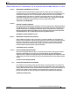
Chapter 2 Installing the Cisco Nexus 3000 Series Switches Starting the Switch S e n d d o c u m e n t c o m m e n t s t o n ex u s 3 k - d o c f e e d b a ck @ c i s c o . c o m Step 5 If you are installing a switch with a DC power supply, connect the power supply to a DC power source as follows: a. Verify that the DC power source is turned off at the circuit breaker. b.
Chapter 2 Installing the Cisco Nexus 3000 Series Switches Starting the Switch Se n d d o c u m e n t c o m m e n t s t o n ex u s 3 k - d o c f e e d b a ck @ c i s c o . c o m e. Connect a positive cable from the power source to the right terminal (is labeled + on newer power supplies [see Callout 2 in Figure 2-8] and - on the first power supplies sold[see Callout 4 in Figure 2-8]) on the power supply and fasten with the screw for that terminal. f.
Chapter 2 Installing the Cisco Nexus 3000 Series Switches Starting the Switch S e n d d o c u m e n t c o m m e n t s t o n ex u s 3 k - d o c f e e d b a ck @ c i s c o .
Se n d d o c u m e n t c o m m e n t s t o n ex u s 3 k - d o c f e e d b a ck @ c i s c o .
Chapter 3 Connecting to the Network Preparing for Network Connections S e n d d o c u m e n t c o m m e n t s t o n ex u s 3 k - d o c f e e d b a ck @ c i s c o .
Chapter 3 Connecting to the Network Connecting to the Management Port Se n d d o c u m e n t c o m m e n t s t o n ex u s 3 k - d o c f e e d b a ck @ c i s c o . c o m Note • Configure SNMP agent parameters. • Download software updates. To connect the console port to a computer terminal, the computer must support VT100 terminal emulation.
Chapter 3 Connecting to the Network Connecting to a Server S e n d d o c u m e n t c o m m e n t s t o n ex u s 3 k - d o c f e e d b a ck @ c i s c o . c o m shorter copper cables, which can connect to another 40-Gigabit QSFP+ port or four 10-Gigabit SFP+ ports. If the servers or switches are further than 16.4 feet (5 meters), it is best to use the optical cable that has 40-Gigabit transceivers on both ends.
Chapter 3 Connecting to the Network Connecting to a Server Se n d d o c u m e n t c o m m e n t s t o n ex u s 3 k - d o c f e e d b a ck @ c i s c o . c o m If you cannot install the cable into the transceiver, insert or leave the dust plug in the cable end of the transceiver. Note Replacing an SFP or SFP+ Transceiver To replace an SFP or SFP+ transceiver, follow these steps: Step 1 Attach an ESD-preventive wrist strap and follow its instructions for use.
Chapter 3 Connecting to the Network Connecting to a Server S e n d d o c u m e n t c o m m e n t s t o n ex u s 3 k - d o c f e e d b a ck @ c i s c o . c o m Installing an Optical Cable into an SFP or SFP+ Transceiver Caution To prevent possible damage to the cable or transceiver, install the transceiver in the port before installing the cable in the transceiver.
Chapter 3 Connecting to the Network Maintaining SFP and SFP+ Transceivers and Fiber-Optic Cables Se n d d o c u m e n t c o m m e n t s t o n ex u s 3 k - d o c f e e d b a ck @ c i s c o . c o m Maintaining SFP and SFP+ Transceivers and Fiber-Optic Cables QSFP+, SFP+, and SFP transceivers and fiber-optic cables must be kept clean and dust-free to maintain high signal accuracy and prevent damage to the connectors. Attenuation (loss of light) is increased by contamination and should be below 0.35 dB.
Chapter 3 Connecting to the Network Maintaining SFP and SFP+ Transceivers and Fiber-Optic Cables S e n d d o c u m e n t c o m m e n t s t o n ex u s 3 k - d o c f e e d b a ck @ c i s c o .
Se n d d o c u m e n t c o m m e n t s t o n ex u s 3 k - d o c f e e d b a ck @ c i s c o . c o m CH A P T E R 4 Replacing Components This chapter describes how to replace the field replaceable units (FRUs) on the Cisco Nexus 3000 Series switch. This chapter includes the following sections: • Replacing a Power Supply, page 4-1 • Replacing a Fan Tray, page 4-4 Replacing a Power Supply The Cisco Nexus 3000 Series switches support a front-end power supply that you can replace.
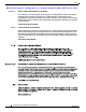
Chapter 4 Replacing Components Replacing a Power Supply S e n d d o c u m e n t c o m m e n t s t o n ex u s 3 k - d o c f e e d b a ck @ c i s c o . c o m To remove an AC power supply, follow these steps: Step 1 Pull the power cord out from the power receptacle on the power supply. Step 2 Release the power supply from the chassis by pushing and holding the thumb latch to the left and pull the power supply part way out of the chassis (see Figure 4-1).
Chapter 4 Replacing Components Replacing a Power Supply Se n d d o c u m e n t c o m m e n t s t o n ex u s 3 k - d o c f e e d b a ck @ c i s c o . c o m Note Step 5 Connect the other end of the power cable to an AC power source. Caution Step 6 Depending on the outlet receptacle on your power distribution unit, you may need the optional jumper power cord to connect the Cisco Nexus 3000 Series switch to your outlet receptacle. See the “Jumper Power Cord” section on page C-8.
Chapter 4 Replacing Components Replacing a Fan Tray S e n d d o c u m e n t c o m m e n t s t o n ex u s 3 k - d o c f e e d b a ck @ c i s c o . c o m Installing a DC Power Supply In a system with dual power supplies, connect each power supply to a separate power source. If a power source failure occurs, the second source will most likely still be available. Caution Be sure that the power supply that you are installing has the same airflow direction as the fan tray module and the other power supply.
Chapter 4 Replacing Components Replacing a Fan Tray Se n d d o c u m e n t c o m m e n t s t o n ex u s 3 k - d o c f e e d b a ck @ c i s c o . c o m Caution Be sure that the replacement fan tray has the correct direction of airflow, which means that it takes in air from the cold aisle and exhausts air to the hot aisle. It must also have the same direction of airflow as the power supplies. Otherwise, an overtemperature condition can occur.
Chapter 4 Replacing Components Replacing a Fan Tray S e n d d o c u m e n t c o m m e n t s t o n ex u s 3 k - d o c f e e d b a ck @ c i s c o . c o m Caution If you are replacing a fan tray during operations, you must insert the new fan tray within 2 minutes of removing the original fan tray. Installing a Fan Tray Caution If you are replacing a fan tray during operations, you must insert the new fan tray within 2 minutes of removing the original fan tray.
Se n d d o c u m e n t c o m m e n t s t o n ex u s 3 k - d o c f e e d b a ck @ c i s c o .
Appendix A Cabinet and Rack Specifications Cabinet and Rack Requirements S e n d d o c u m e n t c o m m e n t s t o n ex u s 3 k - d o c f e e d b a ck @ c i s c o . c o m The cabinet or rack must also meet the following requirements: • The minimum vertical rack space per Cisco Nexus 3000 Series switch chassis must be one RU (rack units), equal to 1.75 inches (4.4 cm). • The minimum vertical rack space per chassis must be one RU (rack unit), equal to 1.75 inches (4.4 cm).
Appendix A Cabinet and Rack Specifications Cable Management Guidelines Se n d d o c u m e n t c o m m e n t s t o n ex u s 3 k - d o c f e e d b a ck @ c i s c o . c o m Cable Management Guidelines To help with cable management, you might want to allow additional space in the rack above and below the chassis to make it easier to route all of the fiber optic or copper cables through the rack.
Appendix A Cabinet and Rack Specifications Cable Management Guidelines S e n d d o c u m e n t c o m m e n t s t o n ex u s 3 k - d o c f e e d b a ck @ c i s c o .
Se n d d o c u m e n t c o m m e n t s t o n ex u s 3 k - d o c f e e d b a ck @ c i s c o . c o m A P P E N D I X B Technical Specifications This appendix describes the technical specifications for the Cisco Nexus 3000 Series switches.
Appendix B Technical Specifications Power Specifications S e n d d o c u m e n t c o m m e n t s t o n ex u s 3 k - d o c f e e d b a ck @ c i s c o .
Appendix B Technical Specifications Power Specifications Se n d d o c u m e n t c o m m e n t s t o n ex u s 3 k - d o c f e e d b a ck @ c i s c o . c o m Table B-3 Specifications for the Cisco Nexus 3000 Series AC Power Supplies (continued) Property AC Power Supply (N2200-PAC-400 W) Output connector DC output connector in the back Supply indicators Supply health: Green LED indicates the power supply is operational and amber LED indicates an error.
Appendix B Technical Specifications Power Specifications S e n d d o c u m e n t c o m m e n t s t o n ex u s 3 k - d o c f e e d b a ck @ c i s c o .
Se n d d o c u m e n t c o m m e n t s t o n ex u s 3 k - d o c f e e d b a ck @ c i s c o . c o m A P P E N D I X C Cable and Connector Specifications This appendix provides cable and port specifications for all of the Cisco Nexus 3000 Series switches.
Appendix C Cable and Connector Specifications Console Port S e n d d o c u m e n t c o m m e n t s t o n ex u s 3 k - d o c f e e d b a ck @ c i s c o . c o m Console Port The console port is an asynchronous RS-232 serial port with an RJ-45 connector. Supported Power Cords and Plugs Each power supply has a separate power cord. Standard power cords or jumper power cords are available for connection to a power distribution unit that has IEC 60320 C19 outlet receptacles.
Appendix C Cable and Connector Specifications Supported Power Cords and Plugs Se n d d o c u m e n t c o m m e n t s t o n ex u s 3 k - d o c f e e d b a ck @ c i s c o . c o m Table C-1 Power Cords for the Cisco Nexus 3000 Series Switches (continued) Length Description Feet Meters Power Cord Reference Illustration CAB-9K10A-UK Power cord 250 VAC 10 A, BS1363 plug (13 A fuse) United Kingdom 8.2 2.5 Figure C-10 CAB-AC-250V/13A Power cord 250 VAC 13 A, NEMA L6-20 plug North America 6.6 2.
Appendix C Cable and Connector Specifications Supported Power Cords and Plugs S e n d d o c u m e n t c o m m e n t s t o n ex u s 3 k - d o c f e e d b a ck @ c i s c o . c o m Figure C-3 CAB-9K10A-AU Connector: EL 701C (IEC 60320/C15) Plug: EL 206 A.S. 3112-2000) SFS-250V-10A-CN Plug: EL 218 (CCEE GB2009) Cordset rating 10A, 250V (2500 mm) Connector: EL 701 (IEC60320/C13) CAB-9K10A-EU Plug: M2511 Cordset rating: 10A/16 A, 250 V Length: 8 ft 2 in. (2.
Appendix C Cable and Connector Specifications Supported Power Cords and Plugs Se n d d o c u m e n t c o m m e n t s t o n ex u s 3 k - d o c f e e d b a ck @ c i s c o .
Appendix C Cable and Connector Specifications Supported Power Cords and Plugs S e n d d o c u m e n t c o m m e n t s t o n ex u s 3 k - d o c f e e d b a ck @ c i s c o .
Appendix C Cable and Connector Specifications Supported Power Cords and Plugs Se n d d o c u m e n t c o m m e n t s t o n ex u s 3 k - d o c f e e d b a ck @ c i s c o . c o m CAB-N5K6A-NA Plug: NEMA 6-15P Cordset rating: 10 A, 250 V Length: 8.2 ft Connector: IEC60320/C13 Figure C-13 186570 Figure C-12 CAB-9K12A-NA Connector: IEC60320/C15 Plug: NEMA 5-15P Figure C-14 192260 Cordset rating 13A, 125V (8.2 feet) (2.
Appendix C Cable and Connector Specifications Jumper Power Cord S e n d d o c u m e n t c o m m e n t s t o n ex u s 3 k - d o c f e e d b a ck @ c i s c o . c o m Figure C-15 CAB-IND-10A Connector EL701B (IEC60320/C13) Plug: EL 208B (IS 6538-1971) 192259 Cordset rating 10A, 250V (8.2 feet) (2.5m) Jumper Power Cord Figure C-16 shows the plug connector on the optional jumper power cord for the Cisco Nexus 3000 Series switches.
Se n d d o c u m e n t c o m m e n t s t o n ex u s 3 k - d o c f e e d b a ck @ c i s c o . c o m A P P E N D I X D LED Descriptions This appendix describes the conditions indicated by the chassis and module LEDs on the Cisco Nexus 3000 Series switches.
Appendix D LED Descriptions Chassis and Module LEDs for the Cisco Nexus 3000 Series Switches S e n d d o c u m e n t c o m m e n t s t o n ex u s 3 k - d o c f e e d b a ck @ c i s c o . c o m Chassis and Module LED Descriptions Table D-1 describes the chassis LEDs for the Cisco Nexus 3000 Series switches. Table D-1 LEDs for the Cisco Nexus 3000 Series Fabric Extenders Component LED Status Description Chassis (front and back) ID On (blue) Identifies the chassis receiving the beacon signal.
Appendix D LED Descriptions Chassis and Module LEDs for the Cisco Nexus 3000 Series Switches Se n d d o c u m e n t c o m m e n t s t o n ex u s 3 k - d o c f e e d b a ck @ c i s c o . c o m Table D-1 LEDs for the Cisco Nexus 3000 Series Fabric Extenders (continued) Component LED Status Description Port LED Indicates LED status Off The port is not active or the link is not connected. Solid on (green) The port is active. The link is connected and operational.
Appendix D LED Descriptions Chassis and Module LEDs for the Cisco Nexus 3000 Series Switches S e n d d o c u m e n t c o m m e n t s t o n ex u s 3 k - d o c f e e d b a ck @ c i s c o . c o m Table D-3 Note Ethernet Port LED Descriptions LED Status Description Right Off No activity Blinking green Activity The Cisco Nexus 3548 switch uses the activity LED to indicate both status and activity. The LED is Off, if there is no cable attached or if the connection is off.
Se n d d o c u m e n t c o m m e n t s t o n ex u s 3 k - d o c f e e d b a ck @ c i s c o . c o m A P P E N D I X E Site Planning and Maintenance Records This appendix provides log sheets that you can use to record information when installing a Cisco Nexus 3000 Series switch.
Appendix E Site Planning and Maintenance Records Site Preparation Checklist S e n d d o c u m e n t c o m m e n t s t o n ex u s 3 k - d o c f e e d b a ck @ c i s c o . c o m Table E-1 Site Planning Checklist Task No.
Appendix E Site Planning and Maintenance Records Contact and Site Information Se n d d o c u m e n t c o m m e n t s t o n ex u s 3 k - d o c f e e d b a ck @ c i s c o . c o m 3. EMI = electromagnetic interference. 4. RFI = radio frequency interference. Contact and Site Information Use the following worksheet (Table E-2) to record contact and site information.
Appendix E Site Planning and Maintenance Records Chassis and Module Information S e n d d o c u m e n t c o m m e n t s t o n ex u s 3 k - d o c f e e d b a ck @ c i s c o . c o m Chassis and Module Information Use the following worksheet (Table E-3) to record information about the chassis and modules.
Se n d d o c u m e n t c o m m e n t s t o n ex u s 3 k - d o c f e e d b a ck @ c i s c o .
Index S e n d d o c u m e n t c o m m e n t s t o n ex u s 3 k - d o c f e e d b a ck @ c i s c o .
Index Se n d d o c u m e n t c o m m e n t s t o n ex u s 3 k - d o c f e e d b a ck @ c i s c o .
Index S e n d d o c u m e n t c o m m e n t s t o n ex u s 3 k - d o c f e e d b a ck @ c i s c o .
Index Se n d d o c u m e n t c o m m e n t s t o n ex u s 3 k - d o c f e e d b a ck @ c i s c o .
Index S e n d d o c u m e n t c o m m e n t s t o n ex u s 3 k - d o c f e e d b a ck @ c i s c o .