Cisco ME 3800X and ME 3600X Switch Hardware Installation Guide October 2010 Americas Headquarters Cisco Systems, Inc. 170 West Tasman Drive San Jose, CA 95134-1706 USA http://www.cisco.
THE SPECIFICATIONS AND INFORMATION REGARDING THE PRODUCTS IN THIS MANUAL ARE SUBJECT TO CHANGE WITHOUT NOTICE. ALL STATEMENTS, INFORMATION, AND RECOMMENDATIONS IN THIS MANUAL ARE BELIEVED TO BE ACCURATE BUT ARE PRESENTED WITHOUT WARRANTY OF ANY KIND, EXPRESS OR IMPLIED. USERS MUST TAKE FULL RESPONSIBILITY FOR THEIR APPLICATION OF ANY PRODUCTS.
Preface Audience This guide is for the person installing the Cisco Metro Ethernet (ME) 3800X and ME 3600X Series switch, also known as the switch. Purpose This guide describes the hardware features of the switch. It describes the physical and performance characteristics of the switch, explains how to install it, and provides troubleshooting information. This guide does not describe system messages that you might receive or how to configure your switch.
Preface Related Publications Warning IMPORTANT SAFETY INSTRUCTIONS This warning symbol means danger. You are in a situation that could cause bodily injury. Before you work on any equipment, be aware of the hazards involved with electrical circuitry and be familiar with standard practices for preventing accidents. Use the statement number provided at the end of each warning to locate its translation in the translated safety warnings that accompanied this device.
Preface Obtaining Documentation and Submitting a Service Request These compatibility matrix documents are available from this Cisco.com site: http://www.cisco.com/en/US/products/hw/modules/ps5455/products_device_support_tables_list.
Preface Obtaining Documentation and Submitting a Service Request Cisco ME 3800X and ME 3600X Switch Hardware Installation Guide vi OL-22168-01
CH A P T E R 1 Product Overview The Cisco Metro Ethernet (ME) 3600X switch is an Ethernet access switch. The Cisco ME 3800X switch is a carrier Ethernet aggregation switch. Throughout this document, the Cisco ME 3800X and ME 3600X are referred to as the switch.
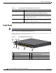
Chapter 1 Product Overview Front Panel Table 1-1 Cisco ME 3800X and ME 3600X Models and Descriptions Switch Model Description Cisco ME-3800X-24FS-M 24 Gigabit Ethernet small form-factor pluggable (SFP) downlink ports and 2 SFP+ (10 Gigabit) uplink ports; supports removable, hot-swappable AC and DC input power supply and fan modules.
Chapter 1 Product Overview Front Panel Figure 1-2 shows the Cisco ME-3600X-24TS-M. The copper 10/100/1000Base-T/TX downlink ports are grouped in pairs. The first member of the pair (port 1) is above the second member (port 2). Port 3 is above port 4, and so on.
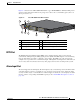
Chapter 1 Product Overview Front Panel Management and Console Port You can connect the switch to a host such as a Windows workstation or a terminal server through the 10/100/1000 Ethernet management port or the console port. The 10/100/1000 Ethernet management port connection uses a standard RJ-45 crossover or straight-through Ethernet cable. The console port connection uses a RJ-45-to-DB-9 female cable.
Chapter 1 Product Overview Front Panel For more information on configuring interfaces, see the switch software configuration guide.
Chapter 1 Product Overview Front Panel SFP Module Patch Cable The SFP downlink ports supports the SFP module patch cable, a 0.5-meter, copper, passive cable with SFP module connectors at each end. This cable is only used with 1-Gigabit Ethernet SFP ports to connect two switches in a cascaded configuration. See the “Inserting and Removing the SFP+ Module Patch Cable” section on page 2-17 for more information about using the SFP module patch cable.
Chapter 1 Product Overview Front Panel Switch LED Panels Figure 1-3 Cisco ME 3800X and ME 3600X Switch LEDs SYST 1 5 PS IN 1 PS IN 2 PS/FAN 1 PS/FAN 2 6 SD CARD 2 3 7 8 9 10 11 12 207445 4 MGMT SYNC ALM 1 ALM 2 ALM 3 ALM 4 1 SYST (system) LED 7 MGMT (Ethernet management port) LED 2 PS IN 1 (power supply module 1 input) LED 8 SYNC LED 3 PS IN 2 (power supply module 2 input) LED 9 ALM 1 (alarm input 1) LED 4 PS/FAN 1 (power supply module output or fan 10 ALM 2 (alarm input 2) LED m
Chapter 1 Product Overview Front Panel Power Supply Module Input LED Description Table 1-5 PS IN 1 and PS IN 2 LEDs Color System Status Off Power supply module (1 or 2) is not installed. Green Power supply module (1 or 2) is installed and receiving power. Amber Power supply module (1 or 2) is installed but not receiving power in an acceptable range.
Chapter 1 Product Overview Front Panel Alarm LEDs Description Table 1-8 Alarm LEDs Color System Status Off No alarm Amber Minor alarm Red Major alarm Blinking red Critical alarm Sync LED Description Table 1-9 Sync LEDs Color System Status Green The synchronous Ethernet internal clocking source is in a synced/locked state from line or BITS timing input. Amber The synchronous Ethernet internal clocking source is in the holdover state.
Chapter 1 Product Overview Rear Panel Port LEDs Description Each RJ-45 port, SFP module slot, and SFP+ module slot has a port LED. These port LEDs, as a group or individually, display information about the switch and about the individual ports. Table 1-11 Port LED LED Color Meaning Off No link, or port was administratively shut down. Green Link present but not sending or receiving data. Blinking green Activity. Port is sending or receiving data. Alternating green-amber Link fault.
Chapter 1 Product Overview Power Supply Module Features Power Supply Module Features The Cisco ME 3800X and ME 3600X switches support two power supply modules, either AC or DC input. You can install two AC or DC input power supply modules, a mix of AC and DC input power supply modules, or one power supply and one fan module. The power supply and fan modules are hot-swappable. Caution Both slots must be occupied either by two power supply modules or a power supply and a fan module.
Chapter 1 Product Overview Fan Module Table 1-12 Power Supply Module Status LED Color System Status Green The power supply module is installed, output is OK, all internal fans OK, and power switch is ON. Red The power supply module is installed, output has failed or one of the internal fans has failed, power switch is ON. Off The power supply module is installed, power switch is OFF, no input power, or invalid input power.
Chapter 1 Product Overview Management Options Fan Module LED Figure 1-6 Fan Module LED 1 207477 FAN 1 Fan module LED Table 1-14 FAN LED Color System Status Green All internal fans are OK. Red One or more internal fans have failed. Off The fan module is not installed, or power is not present. Management Options • Cisco IOS CLI You can fully configure and monitor the switch from the CLI.
Chapter 1 Product Overview Management Options • SNMP network management You can manage switches from a SNMP-compatible management station that is running platforms such as HP OpenView or SunNet Manager. The switch supports a comprehensive set of Management Information Base (MIB) extensions and four Remote Monitoring (RMON) groups. See the switch software configuration guide on Cisco.com and the documentation that came with your SNMP application for more information.
CH A P T E R 2 Switch Installation Read the topics and perform the procedures in this order: • Warnings, page 2-1 • Installation Guidelines, page 2-4 • Verifying Switch Operation, page 2-4 • Installing the Switch, page 2-5 • Installing and Removing SFP+ and SFP Modules, page 2-15 • Inserting and Removing the SFP+ Module Patch Cable, page 2-17 • Connecting to the 10/100/1000 Ports, page 2-19 • Connecting to Fiber-Optic SFP+ and SFP Modules, page 2-20 • Where to Go Next, page 2-20 Warnings
Chapter 2 Switch Installation Warnings Note Ethernet cables must be shielded and grounded at both ends when they are used in a central office environment. Warning Do not work on the system or connect or disconnect cables during periods of lightning activity. Statement 1001 Warning Read the installation instructions before connecting the system to the power source.
Chapter 2 Switch Installation Warnings Warning Only trained and qualified personnel should be allowed to install, replace, or service this equipment. Statement 1030 Warning Ultimate disposal of this product should be handled according to all national laws and regulations. Statement 1040 Warning For connections outside the building where the equipment is installed, the following ports must be connected through an approved network termination unit with integral circuit protection.
Chapter 2 Switch Installation Installation Guidelines Installation Guidelines Before installing the switch, verify that these guidelines are met: • For Ethernet ports and 1000BASE-T SFP module ports, cable lengths from the switch to connected devices can be up to 328 feet (100 meters). • For cable requirements for SFP+ and SFP module connections, see the “Cable Pinouts” section on page B-7. • Operating environment is within the ranges listed in Appendix A, “Technical Specifications.
Chapter 2 Switch Installation Installing the Switch Powering Off the Switch After a successful POST, disconnect the power cord from the switch. Install the switch in a rack, on a wall, on a table, or on a shelf as described in the “Installing the Switch” section on page 2-5.
Chapter 2 Switch Installation Installing the Switch Attaching Brackets to the Switch The bracket orientation and the brackets that you use depend on whether you are attaching the brackets for a 19-inch, 23-inch, or an ETSI rack. Figure 2-1 shows the types of mounting brackets.
Chapter 2 Switch Installation Installing the Switch Attaching Brackets for 19-Inch Racks Figure 2-2 shows how to attach brackets for 19-inch racks on the switch.
Chapter 2 Switch Installation Installing the Switch Attaching Brackets for 23-Inch Racks Figure 2-3 shows how to attach brackets for the 23-inch racks on the switch.
Chapter 2 Switch Installation Installing the Switch Attaching Brackets for ETSI Racks Figure 2-4 shows how to attach brackets for the ETSI racks on the switch.
Chapter 2 Switch Installation Installing the Switch Attaching Angle Brackets for 23-Inch Racks Figure 2-3 shows how to attach the angle brackets for 23-inch racks on the switch. Note Use the holes marked R to install the bracket on the right side; use the holes marked L to install the bracket on the left side.
Chapter 2 Switch Installation Installing the Switch Mounting in a Rack After the brackets are attached on the switch, use the four supplied number-12 Phillips machine screws to securely attach the brackets to the rack. See Figure 2-6 for standard rack-mounting using the 19-inch, 23-inch, and ETSI brackets. See Figure 2-7 for rack-mounting using the angle-bracket.
Chapter 2 Switch Installation Installing the Switch Mounting the Switch Using 23-Inch Angle Brackets This warning applies to rack-mounted switches that use angle brackets: Warning Note Suitable for mounting on and over a concrete or other non-combustible surface only. Statement 345 The front of the switch extends approximately 5 inches from the front of the rack (including space for cables), and the rear of the switch extends approximately 10 inches into the rack.
Chapter 2 Switch Installation Installing the Switch After the switch is mounted in the rack, you need to do these tasks to complete the installation: • Power on the switch. See the “Verifying Switch Operation” section on page 2-4. • Connect to the console port, and run the initial configuration. See the Cisco ME 3800X and ME 3600X Switch Getting Started Guide for instructions. • Connect to the front-panel ports.
Chapter 2 Switch Installation Installing the Switch Mounting the Switch on a Wall For the best support of the switch and cables, make sure that the switch is attached securely to wall studs or to a firmly attached plywood mounting backboard. Warning Read the wall-mounting instructions carefully before beginning installation. Failure to use the correct hardware or to follow the correct procedures could result in a hazardous situation to people and damage to the system.
Chapter 2 Switch Installation Installing and Removing SFP+ and SFP Modules Table- or Shelf-Mounting Follow these steps to install the switch on a table or a shelf: Step 1 Place the switch on a table or a shelf near an AC power source. Step 2 After the switch is placed on the table or shelf, you need to do these tasks to complete the installation: • Power on the switch. See the “Verifying Switch Operation” section on page 2-4. • Connect to the console port, and run the initial configuration.
Chapter 2 Switch Installation Installing and Removing SFP+ and SFP Modules Step 1 Attach an ESD-preventive wrist strap to your wrist and to a bare metal surface. Step 2 Find the send (TX) and receive (RX) markings that identify the top side of the SFP+ or SFP module. On some SFP+ and SFP modules, the send and receive (TX and RX) markings might be replaced by arrows that show the direction of the connection, either send or receive (TX or RX).
Chapter 2 Switch Installation Inserting and Removing the SFP+ Module Patch Cable Figure 2-12 Removing a Bale-Clasp Latch SFP+ Module 2 207470 1 1 1 Bale clasp Step 5 Grasp the SFP+ or SFP module, and carefully remove it from the module slot. Step 6 For fiber-optic SFP+ or SFP modules, insert a dust plug into the optical ports of the SFP+ or SFP module to keep the optical interfaces clean. Step 7 Place the removed SFP+ or SFP module in an antistatic bag or other protective environment.
Chapter 2 Switch Installation Inserting and Removing the SFP+ Module Patch Cable Figure 2-13 Inserting an SFP+ Module Patch Cable into an SFP+ Module Slot 2 Repeat these steps for the second switch to which you want to connect the first switch.
Chapter 2 Switch Installation Connecting to the 10/100/1000 Ports Connecting to the 10/100/1000 Ports The switch 10/100/1000 ports configure themselves to operate at the speed of attached devices. If the attached ports do not support autonegotiation, you can explicitly set the speed and duplex parameters. Connecting devices that do not autonegotiate or that have their speed and duplex parameters manually set can reduce performance or result in no linkage.
Chapter 2 Switch Installation Connecting to Fiber-Optic SFP+ and SFP Modules Connecting to Fiber-Optic SFP+ and SFP Modules Warning Caution Class 1 laser product. Statement 1008 Do not remove the rubber plugs from the SFP+ or SFP module port or the rubber caps from the fiber-optic cable until you are ready to connect the cable. The plugs and caps protect the SFP+ or SFP module ports and cables from contamination and ambient light.
CH A P T E R 3 Installing and Removing AC and DC Input Power Supply and Fan Modules This chapter provides the installation and removal instructions for the AC and DC input power supply and fan modules for the Cisco ME 3800X and ME 3600X switches. Your switch ships with at least one power supply module installed, either AC or DC, depending on your order. The power supply and fan modules are field-replaceable units (FRUs). Note The power supply and fan modules are hot-swappable devices.
Chapter 3 Installing and Removing AC and DC Input Power Supply and Fan Modules Power Supply Module Description Each power supply module is cooled by three internal fans. A fan failure triggers an alarm. When a fan fails, replace the power supply module immediately. Caution Both slots must be occupied either by two power supply modules or a power supply and a fan module. Do not run the switch with an empty slot unless you are replacing a faulty power supply or fan module.
Chapter 3 Installing and Removing AC and DC Input Power Supply and Fan Modules Fan Module Description Fan Module Description Table 3-2 Fan Module Model Number and Description Model number Description ME-FANTRAY Fan module The fan module provides cooling and proper airflow when only one power supply module is installed. Caution Both slots must be occupied either by two power supply modules or a power supply and a fan module.
Chapter 3 Installing and Removing AC and DC Input Power Supply and Fan Modules Power Supply and Fan Module Installation Figure 3-4 Power Supply and Fan Module Connector Side 1 1 207449 1 2 1 Fans 2 Connector pins Power Supply and Fan Module Installation • Equipment That You Supply, page 3-4 • Installation Guidelines, page 3-4 • Installing an AC Power Supply Module, page 3-5 • Installing a DC Power Supply Module, page 3-7 • Installing a Fan Module, page 3-13 Equipment That You Supply Y
Chapter 3 Installing and Removing AC and DC Input Power Supply and Fan Modules Power Supply and Fan Module Installation Warning Caution Do not work on the system or connect or disconnect cables during periods of lightning activity. Statement 1001 To prevent overheating and to maintain proper air flow, either a power supply module or a fan module must be installed in each power supply module slot at all times.
Chapter 3 Installing and Removing AC and DC Input Power Supply and Fan Modules Power Supply and Fan Module Installation Step 5 (Optional) Attach the power-cord retainer clip to the power supply module and thread the plastic bushing until it is snug against the plug (Figure 3-7). AC Power Supply Module and Power-Cord Retainer in a Switch 278366 Figure 3-7 Step 6 Turn on the power at the power source and set the power supply module switch to ON.
Chapter 3 Installing and Removing AC and DC Input Power Supply and Fan Modules Power Supply and Fan Module Installation Installing a DC Power Supply Module This procedure is for installing an DC power supply module into the PSU 1 power supply module slot. Repeat these steps to install a power supply module in the PSU 2 power supply slot. To connect the switch to a DC input power source, follow these steps: 1. Preparing for Installation, page 3-7 2. Grounding the Switch, page 3-8 3.
Chapter 3 Installing and Removing AC and DC Input Power Supply and Fan Modules Power Supply and Fan Module Installation Grounding the Switch Follow the grounding procedure instructions and observe these warnings: Warning This equipment must be grounded. Never defeat the ground conductor or operate the equipment in the absence of a suitably installed ground conductor. Contact the appropriate electrical inspection authority or an electrician if you are uncertain that suitable grounding is available.
Chapter 3 Installing and Removing AC and DC Input Power Supply and Fan Modules Power Supply and Fan Module Installation Crimping the Ground Lug 280938 Figure 3-9 Step 5 Attach the dual-hole lug and the wire assembly to the chassis ground connection with the supplied screws (Figure 3-10). Attaching the Ground Lug and Wire Assembly 207475 Figure 3-10 1 1 Dual-hole ground lug Step 6 Use a ratcheting torque Phillips-head screwdriver to torque the ground-lug screws to 32 in-lb.
Chapter 3 Installing and Removing AC and DC Input Power Supply and Fan Modules Power Supply and Fan Module Installation Installing the DC Power Supply Module in the Switch Step 1 To ensure that power is removed from the DC circuits, locate the circuit breakers for the DC circuits, switch the circuit breakers to the OFF position, and tape the circuit-breaker switches in the OFF position.
Chapter 3 Installing and Removing AC and DC Input Power Supply and Fan Modules Power Supply and Fan Module Installation Step 1 To ensure that all power is OFF, locate the circuit breaker that services the DC circuit, switch the circuit breaker to the OFF position, and tape the switch handle of the circuit breaker in the OFF position. Step 2 Remove the terminal block cover. Note Step 3 The terminal block is covered by a clear plastic block cover that snaps onto the terminal block.
Chapter 3 Installing and Removing AC and DC Input Power Supply and Fan Modules Power Supply and Fan Module Installation Caution Secure the wires coming from the terminal block so that they cannot be disturbed. For example, use tie wraps to secure the wires to the rack. Step 7 After ensuring that all wire connections are secure, reinstall the terminal block cover. Step 8 Remove the tape from the circuit-breaker switch handle, and move the circuit-breaker handle to ON.
Chapter 3 Installing and Removing AC and DC Input Power Supply and Fan Modules Power Supply and Fan Module Installation Installing a Fan Module Step 1 Insert the new fan module in the power supply module slot, and gently push it into the slot (Figure 3-14). When correctly inserted, the fan module is flush with the switch rear panel. Inserting a Fan Module in a Switch 207480 Figure 3-14 Step 2 Align the two captive screws with the screw holes in the panel.
Chapter 3 Installing and Removing AC and DC Input Power Supply and Fan Modules Power Supply and Fan Module Installation Cisco ME 3800X and ME 3600X Switch Hardware Installation Guide 3-14 OL-22168-01
CH A P T E R 4 Troubleshooting • Diagnosing Problems, page 4-1 • Clearing the Switch IP Address and Configuration, page 4-4 • Finding the Switch Serial Number, page 4-5 Diagnosing Problems The LEDs on the front panel provide troubleshooting information about the switch. They show power-on self-test (POST) failures, port-connectivity problems, and overall switch performance. You can also get statistics from the CLI or from an SNMP workstation.
Appendix 4 Troubleshooting Diagnosing Problems Switch LEDs You must have physical access to the switch to do this. Look at the port LEDs for troubleshooting information about the switch. See the “LEDs” section on page 1-6 for a description of the LED colors and their meanings. Switch Connections Bad or Damaged Cable Always examine the cable for marginal damage or failure.
Appendix 4 Troubleshooting Diagnosing Problems • Verify that you are using the correct cable type. See Appendix B, “Connector and Cable Specifications,” for more information. • Look for loose connections. Sometimes a cable appears to be seated, but is not. Disconnect the cable and then reconnect it. SFP+ and SFP Module Port Issues Use only Cisco SFP+ and SFP modules on the switch. Each Cisco module has an internal serial EEPROM that is encoded with security information.
Appendix 4 Troubleshooting Clearing the Switch IP Address and Configuration Switch Performance Speed, Duplex, and Autonegotiation If the port statistics show a large amount of alignment errors, frame check sequence (FCS), or late-collisions errors, this might mean a speed or duplex mismatch. A common issue with speed and duplex is when the duplex settings are mismatched between two switches, between a switch and a router, or between the switch and a workstation or server.
Appendix 4 Troubleshooting Finding the Switch Serial Number To reset the switch: 1. At the switch prompt, enter enable, and press Return or Enter. 2. At the privileged EXEC prompt, switch#, enter setup, and press Return or Enter. The switch displays the prompt to run the initial configuration dialog. The switch now behaves like an unconfigured switch. You can configure the switch by using the CLI setup procedure described in Appendix C, “Configuring the Switch with the CLI-Based Setup Program.
Appendix 4 Troubleshooting Finding the Switch Serial Number Cisco ME 3800X and ME 3600X Switch Hardware Installation Guide 4-6 OL-22168-01
A P P E N D I X A Technical Specifications • Environmental and Technical Specifications for the Switch, page A-1 • Environmental and Technical Specifications for the Power Supply and Fan Modules, page A-5 Environmental and Technical Specifications for the Switch Table A-1 Environmental Ranges for the Switch Environmental Ranges Operating Environment and Altitude1, 2 Normal Operating Ambient Air Temperature and Altitudes • 23° to 122°F (–5º to 50ºC), up to 1,000 feet (300 m) • 23° to 113°F (–5º t
Appendix A Technical Specifications Environmental and Technical Specifications for the Switch 4. Acoustic noise is measured per ISO 7779 and declared per ISO 9296. 5. This can be limited by specification of optical modules. Table A-2 Technical Specifications—ME-3800X-24FS-M Physical Dimensions Weight 14.50 lb (6.58 kg) (no FRU installed) Dimensions (H x W x D) 1.72 x 17.50 x 20.39 in. (4.37 x 44.45 x 51.79 cm) AC Power Requirements Input voltage 100 to 240 VAC ± 10% (autoranging), 50 to 60 Hz.
Appendix A Technical Specifications Environmental and Technical Specifications for the Switch Table A-3 Technical Specifications—ME-3600X-24FS-M Physical Dimensions Weight 14.50 lb (6.58 kg) (no FRU installed) Dimensions (H x W x D) 1.72 x 17.50 x 20.39 in. (4.37 x 44.45 x 51.79 cm) AC Power Requirements Input voltage 100 to 240 VAC ± 10% (autoranging), 50 to 60 Hz. Power consumption with 1 AC power Total: 762 BTUs per hour (maximum).
Appendix A Technical Specifications Environmental and Technical Specifications for the Switch Table A-4 Technical Specifications—ME-3600X-24TS-M Physical Dimensions Weight 14.15 lb (6.42 kg) (no FRU installed) Dimensions (H x W x D) 1.72 x 17.50 x 20.39 in. (4.37 x 44.45 x 51.79 cm) AC Power Requirements Input voltage 100 to 240 VAC ± 10% (autoranging), 50 to 60 Hz. Power consumption with 1 AC power Total: 656 BTUs per hour (maximum).
Appendix A Technical Specifications Environmental and Technical Specifications for the Power Supply and Fan Modules Environmental and Technical Specifications for the Power Supply and Fan Modules Table A-5 Environmental and Physical Specifications for the AC and DC Input Power Supply and Fan Modules Environmental Ranges Operating temperature –40 to 122°F (–40 to 50°C) Storage temperature –49 to 185°F (–45 to 85°C) Relative humidity 5 to 95% (noncondensing) Altitude Up to 10,000 ft (3049 m) Physi
Appendix A Technical Specifications Environmental and Technical Specifications for the Power Supply and Fan Modules Cisco ME 3800X and ME 3600X Switch Hardware Installation Guide A-6 OL-22168-01
A P P E N D I X B Connector and Cable Specifications • Connector Specifications, page B-1 • Cables and Adapters, page B-5 Connector Specifications • 10/100/1000, page B-1 • SFP and SFP+ Module Connectors, page B-2 • 10/100/1000 Ethernet Management Port, page B-3 • Alarm Input Port, page B-3 • BITS Port, page B-4 10/100/1000 The 10/100/1000 Ethernet ports use standard RJ-45 connectors and Ethernet pinouts.
Appendix B Connector and Cable Specifications Connector Specifications SFP and SFP+ Module Connectors Figure B-2, Figure B-3, and Figure B-4 show the SFP module connectors. The Cisco ME 3800X and ME 3600X switches support the SFP module patch cable, a 0.5-meter, copper, passive cable with SFP module connectors at each end (Figure B-5). The patch cable can connect two Cisco ME 3800X and ME 3600X switches in a cascaded configuration.
Appendix B Connector and Cable Specifications Connector Specifications SFP Module Patch Cable 126809 Figure B-5 10/100/1000 Ethernet Management Port The 10/100/1000 Ethernet management port uses standard RJ-45 connectors with Ethernet pinouts. 10/100/1000 Port Pinouts Pin Label 1 TP0+ 2 TP0- 3 TP1+ 4 TP2+ 5 TP2- 6 TP1- 7 TP3+ 8 TP3- 1 2 3 4 5 6 7 8 60915 Figure B-6 Alarm Input Port The alarm input port uses a standard RJ-45 connector.
Appendix B Connector and Cable Specifications Connector Specifications Figure B-7 Alarm connection 1 Alarm 1 input 2 Alarm 2 input 3 no connection 4 Alarm 3 input 5 Alarm 4 input 6 no connection 7 no connection 8 Alarm common 1 2 3 4 5 6 7 8 280950 Pin Alarm Input Port Pinouts BITS Port Note We recommend using a shielded cable for the BITS port.
Appendix B Connector and Cable Specifications Cables and Adapters Cables and Adapters • SFP and SFP+ Module Cabling, page B-5 • Cable Pinouts, page B-7 • Console Port Adapter Pinouts, page B-8 SFP and SFP+ Module Cabling Each port must match the wave-length specifications on the other end of the cable, and for reliable communications, the cable must not exceed the required cable length.
Appendix B Connector and Cable Specifications Cables and Adapters Table B-2 Fiber-Optic SFP Module Port Cabling Specifications (continued) Wavelength (nanometers) SFP Module Fiber Type Core Modal Size/Cladding Bandwidth Size (micron) (MHz/km)1 Cable Distance DWDM 1560.61, 1559.79, 1558.98, 1558.17, 1556.55, 1554.55, 1554.94, 1554.13, 1552.13, 1551.72, 1550.92, 1550.12, 1548.51, 1547.72, 1546.92, 1546.12, 1546.12, 1544.53, 1543.73, 1542.94, 1542.14, 1540.56, 1539.77, 1538.98, 1536.61, 1535.
Appendix B Connector and Cable Specifications Cables and Adapters Cable Pinouts Two Twisted-Pair Straight-Through Cable Schematic Switch Router or PC 3 TD+ 6 TD– 3 RD+ 6 RD– 1 RD+ 2 RD– 1 TD+ 2 TD– Two Twisted-Pair Crossover Cable Schematic Switch Switch 3 TD+ 6 TD– 3 TD+ 6 TD– 1 RD+ 2 RD– 1 RD+ 2 RD– Four Twisted-Pair Straight-Through Cable Schematic for 1000BASE-T Ports Switch Router or PC 1 TP0+ 1 TP0+ 2 TP0- 2 TP0- 3 TP1+ 3 TP1+ 6 TP1- 6 TP1- 4 TP2+ 4 TP2+ 5 TP2- 5 TP2- 7
Appendix B Connector and Cable Specifications Cables and Adapters Four Twisted-Pair Crossover Cable Schematics for 1000BASE-T Ports Switch Switch 1 TP0+ 1 TP0+ 2 TP0- 2 TP0- 3 TP1+ 3 TP1+ 6 TP1- 6 TP1- 4 TP2+ 4 TP2+ 5 TP2- 5 TP2- 7 TP3+ 7 TP3+ 8 TP3- 8 TP3- 65274 Figure B-11 To identify a crossover cable, compare the two modular ends of the cable. Hold the cable ends side-by-side, with the tab at the back.
Appendix B Connector and Cable Specifications Cables and Adapters Table B-3 lists the pinouts for the console port, the RJ-45-to-DB-9 adapter cable, and the console device.
Appendix B Connector and Cable Specifications Cables and Adapters Cisco ME 3800X and ME 3600X Switch Hardware Installation Guide B-10 OL-22168-01
A P P E N D I X C Configuring the Switch with the CLI-Based Setup Program This appendix provides a CLI-based setup procedure for a standalone switch. Before connecting the switch to a power source, review the safety warnings in Chapter 2, “Switch Installation” and Chapter 3, “Installing and Removing AC and DC Input Power Supply and Fan Modules.
Appendix C Configuring the Switch with the CLI-Based Setup Program Entering the Initial Configuration Information To power on the switch, connect one end of the AC power cord to the AC power connector on the switch, and connect the other end of the power cord to an AC power outlet. To power on a DC switch, see Chapter 3, “Installing and Removing AC and DC Input Power Supply and Fan Modules.
Appendix C Configuring the Switch with the CLI-Based Setup Program Entering the Initial Configuration Information Step 3 Enter an enable secret password, and press Return. The password can be from 1 to 25 alphanumeric characters, can start with a number, is case sensitive, allows spaces, but ignores leading spaces. The secret password is encrypted and the enable password is in plain text. Enter enable secret: secret_password Step 4 Enter an enable password, and press Return.
Appendix C Configuring the Switch with the CLI-Based Setup Program Entering the Initial Configuration Information Step 8 Configure the interface by entering the switch IP address and subnet mask and pressing Return. The IP address and subnet masks shown below are examples. Configuring interface vlan1: Configure IP on this interface? [yes]: yes IP address for this interface: 10.4.120.106 Subnet mask for this interface [255.0.0.0]: 255.0.0.