
- Cisco IE 2000 Switch Manual


B-1
Cisco IE 2000 Switch Hardware Installation Guide
OL-25818-04
APPENDIX
B
Cable and Connectors
• Connector Specifications, page B-1
• Cables and Adapters, page B-4
Connector Specifications
• 10/100 Ports, page B-1
• SFP Module Connectors, page B-2
• Dual-Purpose Ports, page B-2
• Alarm Port, page B-3
10/100 Ports
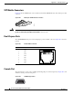
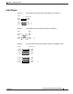
The 10/100 Ethernet ports on the switches use RJ-45 connectors. Figure B-1 shows the pinouts.
Figure B-1 10/100 Port Pinouts
Note For the three models of IE 2000 switch that support PoE, connector pins 4 and 5 supply +48 VDC and
pins 7 and 8 are the DC voltage return lines.
H5318
2 31 45678Pin Label
1
2
3
4
5
6
7
8
RD+
RD-
TD+
NC
NC
TD-
NC
NC