Cisco CGS 2520 Hardware Installation Guide August 2011 Americas Headquarters Cisco Systems, Inc. 170 West Tasman Drive San Jose, CA 95134-1706 USA http://www.cisco.
THE SPECIFICATIONS AND INFORMATION REGARDING THE PRODUCTS IN THIS MANUAL ARE SUBJECT TO CHANGE WITHOUT NOTICE. ALL STATEMENTS, INFORMATION, AND RECOMMENDATIONS IN THIS MANUAL ARE BELIEVED TO BE ACCURATE BUT ARE PRESENTED WITHOUT WARRANTY OF ANY KIND, EXPRESS OR IMPLIED. USERS MUST TAKE FULL RESPONSIBILITY FOR THEIR APPLICATION OF ANY PRODUCTS. THE SPECIFICATIONS AND INFORMATION REGARDING THE PRODUCTS IN THIS MANUAL ARE SUBJECT TO CHANGE WITHOUT NOTICE.
CONTENTS Preface vii Related Publications i-viii Obtaining Documentation and Submitting a Service Request CHAPTER 1 Product Overview 1-1 Switch Models 1-1 i-viii Cable Side 1-2 10/100 Fast Ethernet Ports 1-3 PoE Ports 1-3 Dual-Purpose Ports 1-4 SFP Modules 1-4 SFP Module Patch Cable 1-5 Power-Input Terminal 1-6 Alarm Ports 1-6 Alarm Input 1-6 Alarm Output 1-6 Management Ports 1-6 LEDs 1-7 Switch Panel LEDs 1-8 System LED 1-8 Power Supply Module LEDs 1-9 Alarm LEDs 1-9 Console LEDs 1-9 Port LEDs
Contents CHAPTER 2 Switch Installation Warnings 2-1 2-1 Installation Guidelines 2-3 Verifying Switch Operation 2-3 Installing the Switch 2-4 Mounting into a Rack 2-4 .
Contents CHAPTER 4 Troubleshooting 4-1 Diagnosing Problems 4-1 Switch POST Results 4-1 Switch LEDs 4-1 Switch Connections 4-2 Bad or Damaged Cable 4-2 Ethernet and Fiber-Optic Cables 4-2 Link Status 4-2 10/100 and 10/100/1000 Port Connections 4-2 10/100 PoE Port Connections 4-3 SFP Module 4-3 Interface Settings 4-3 Ping End Device 4-3 Spanning Tree Loops 4-4 Switch Performance 4-4 Speed, Duplex, and Auto-Negotiation 4-4 Auto-Negotiation and Network Interface Cards 4-4 Cabling Distance 4-4 Resetting the
Contents RJ-45 Console Port C-1 USB Console Port C-3 Installing the Cisco Microsoft Windows USB Device Drivers C-4 Installing the Cisco Microsoft Windows XP USB Driver C-4 Installing the Cisco Microsoft Windows 2000 USB Driver C-4 Installing the Cisco Microsoft Windows Vista USB Driver C-5 Uninstalling the Cisco Microsoft Windows USB Drivers C-5 Uninstalling the Cisco Microsoft Windows XP and 2000 USB Driver Uninstalling the Cisco Microsoft Windows Vista USB Driver C-6 Entering the Initial Configuration In
Preface This guide describes the hardware features of the Cisco Connected Grid Switch (CGS) 2520. It describes the physical and performance characteristics of the switch, explains how to install it, and provides troubleshooting information. This guide does not describe system messages that you might receive or how to configure your switch. See the switch software configuration guide, the switch command reference, and the switch system message guide on Cisco.com: http://www.cisco.
Preface Related Publications Related Publications http://www.cisco.com/go/cgs2520_docs Note Before installing, configuring, or upgrading the switch, see the release notes on Cisco.com for the latest information.
CH A P T E R 1 Product Overview The Cisco CGS 2520 switches, also referred to as the switch, are Ethernet switches that you can connect devices such as Intelligent Electronic Devices (IEDs), distributed controllers, substation routers, Cisco IP Phones, Cisco Wireless Access Points, and other network devices such as redundant substation switches.
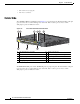
Chapter 1 Product Overview Cable Side 1. SFP = small-form-factor pluggable. 2. PoE = Power over Ethernet. Cable Side The 10/100 Fast Ethernet downlink ports in Figure 1-1 are grouped in pairs. The first member of the pair (port 1) is above the second member (port 2) on the left. Port 3 is above port 4, and so on. The dual-purpose ports are numbered 1 and 2.
Chapter 1 Product Overview Cable Side Figure 1-2 Cisco CGS-2520-16S-8PC Cable-Side View 1 3 5 6 7 8 9 POWER OVER ETH 207197 ERNET POWER OVER ETH ERNET Cisco CGS 4 2 2520 10 1 SD flash memory card slot 6 Dual purpose ports 2 LEDs 7 RJ-45 console port 3 Express Setup button 8 USB (mini-Type B) console port 4 100BASE-FX SFP ports 9 Power-input terminal 5 10/100 PoE ports 10 Alarm port 10/100 Fast Ethernet Ports You can set the 10/100 ports on the switch to operate in any
Chapter 1 Product Overview Cable Side PoE ports. When both the power supply modules are installed, the system has enough power to support all the eight ports as PoE ports. In case one of the power supply module fails, the power to the low priority PoE ports is dropped, while power to the high priority PoE ports remains uninterrupted. On a per-port basis, you control whether or not a port automatically provides power when an IP phone or an access point is connected.
Chapter 1 Product Overview Cable Side Table 1-2 Maximum Operating Temperature Type of SFP Module Rugged and Industrial SFPs –40 to 140°F (–40 to 60°C) Commercial SFPs 32 to 113°F (0 to 45°C) Extended temperature SFPs 23 to 140°F (–5 to 60°C) Model • GLC-SX-MM-RGD • GLC-LX-SM-RGD • GLC-FE-100LX-RGD • GLC-FE-100FX-RGD • GLC-ZX-SM-RGD • GLC-BX-D with DOM support • GLC-BX-U with DOM support • GLC-FE-100LX • GLC-FE-100BX-D • GLC-FE-100BX-U • GLC-FE-100FX • GLC-FE-100EX • GLC-FE-10
Chapter 1 Product Overview Cable Side Power-Input Terminal The power-input terminal provides screw terminals for the AC and DC power connections. The switch can operate with one or two power supplies. If one of the power sources fail, the other continues to power the switch. See Power Supply Installation, page 3-1 for information. Figure 1-4 Power-Input Terminal 207234 Cisco CG S 2520 Alarm Ports The switch has four alarm inputs and one alarm output. The alarm setting is open or closed.
Chapter 1 Product Overview Cable Side • USB mini-Type B console port (5-pin connector); the USB connection uses a USB Type A-to-5-pin mini-Type B cable The USB console interface speeds are the same as the RJ-45 console interface speeds. To use the USB console port, you must install the Cisco Windows USB device driver on the device that is connected to the USB console port (device running with Microsoft Windows).
Chapter 1 Product Overview Cable Side Switch Panel LEDs Figure 1-6 2 3 4 5 6 7 8 9 10 11 12 13 207198 1 Switch LEDs (Cable Side) 14 15 16 1 SYS (system) 9 2 CON (console) 10 PSU1 (power supply 1) 3 USB 11 PSU2 (power supply 2) 4 SD (SD flash memory card) 12 PoE1 5 IN1 (alarm input 1) 13 Express Setup button 6 IN2 (alarm input 2) 14 Ethernet ports 7 IN3 (alarm input 3) 15 SFP module port 8 IN4 (alarm input 4) 16 10/100/1000 port OUT (alarm output) 1.
Chapter 1 Product Overview Cable Side Power Supply Module LEDs The switch power supply module LEDs are labeled PSU1 and PSU2 (on the switch) and PSU OK (on the power supply module). They show whether power supply modules 1 and 2 are receiving power. See Figure 1-6 and Figure 1-9.
Chapter 1 Product Overview Cable Side Port LEDs RJ-45 ports and SFP-module slots have port LEDs. Port LEDs, as a group or individually, provide information about the switch and about the individual ports. Table 1-8 Meaning of Port LED Colors LED Color Meaning Off No link or port was administratively shut down Green Link present but not sending or receiving data Blinking green Activity. Port is sending or receiving data Alternating green-amber Link fault.
Chapter 1 Product Overview Power Supply Side Table 1-10 SD Flash Memory Card LED (continued) Color System Status Amber Error accessing the SD flash memory card; Cisco IOS boot image cannot be found Green SD flash memory card is functioning SD Flash Memory Card The switch ships with the Secure Digital (SD) flash memory card installed. See Figure 1-1 and Figure 1-2. You can remove the card from a failed switch and install it in a replacement switch. You do not have to reconfigure the new switch.
Chapter 1 Product Overview Power Supply Side Figure 1-8 Switch with Both Power Supply Modules 207230 PWR-RGD-LOW-DC PWR-RGD-LOW-DC Cisco Conn ected Grid Switch 2500 Series 1 1 1 PSU OK LED For a description of the PSU OK LED, see Table 1-4 on page 1-9.
Chapter 1 Product Overview Management Options 1. Only on the Cisco CGS-2520-16S-8PC switch. For a description of the LEDs, see LEDs, page 1-7.
Chapter 1 Product Overview Management Options • Cisco Configuration Engine The Cisco Configuration Engine automates initial configurations and configuration updates. It generates device-specific configuration changes, sends them to the device, executes the configuration changes, and logs the results. For information about Cisco Configuration Engine, see the software configuration guide on Cisco.com.
CH A P T E R 2 Switch Installation This chapter contains the steps to install the switch.
Chapter 2 Switch Installation Warnings Warning This unit is intended for installation in restricted access areas. A restricted access area can be accessed only through the use of a special tool, lock and key, or other means of security. Statement 1017 Warning This equipment must be grounded. Never defeat the ground conductor or operate the equipment in the absence of a suitably installed ground conductor.
Chapter 2 Switch Installation Installation Guidelines Warning To prevent airflow restriction, allow clearance around the ventilation openings to be at least: 1.75 in. (4.4 cm). Statement 1076 Installation Guidelines Before installing the switch, verify that these guidelines are met: • Cabling must be kept away from sources of electrical noise, such as radios, power lines, and fluorescent lighting fixtures. Make sure that the cabling is away from other devices that might damage the cables.
Chapter 2 Switch Installation Installing the Switch Installing the Switch The following installation information is covered in this section: Note • Mounting into a Rack, page 2-4 • Wall-Mounting, page 2-16 After the switch is mounted onto the rack, connect the power source to the switch. See Power Supply Installation, page 3-1 Mounting into a Rack The following mounting procedures are explained in this section: Warning • .
Chapter 2 Switch Installation Installing the Switch Figure 2-2 shows the 23-inch rack mounting brackets. Figure 2-2 23-inch Mounting Brackets Figure 2-3 shows the ETSI rack mounting brackets. Figure 2-3 ETSI Mounting Brackets Attaching Brackets for 19-Inch Racks Figure 2-4 and Figure 2-5 shows the 19-inch rack mounting bracket locations on the switch for cable-side mounting and power-side mounting onto an 19-inch rack.
Chapter 2 Switch Installation Installing the Switch Figure 2-4 Attaching Brackets for 19-Inch Racks 1 Mid-mount position 3 Cable-side mounting position 2 Phillips flat-head screws 4 Power supply-side mounting position Cisco CGS 2520 Hardware Installation Guide 2-6 78-19377-02
Chapter 2 Switch Installation Installing the Switch Figure 2-5 Attaching Brackets for 19-Inch Racks 1 Phillips flat-head screws 2 Cable-side-mounting position 3 Power supply-side mounting position Attaching Brackets for 19-Inch Racks (IP-30 Compliance) Before installing the mounting brackets, you need to install the rubber plugs into the unused mounting holes of the switch chassis. You can get the appropriate rubber plugs by ordering kit CGS-2520-IP30KIT.
Chapter 2 Switch Installation Installing the Switch Figure 2-6 Inserting the Rubber Plugs 1 Rubber plug 3 Cable-side mounting position 2 Mid-mount position 4 Power supply-side mounting position Cisco CGS 2520 Hardware Installation Guide 2-8 78-19377-02
Chapter 2 Switch Installation Installing the Switch Figure 2-7 Step 3 Inserting the Rubber Plugs 1 Rubber plug 2 Cable-side mounting position 3 Power supply-side mounting position Use a screwdriver or pen to completely push in the rubber plugs. Figure 2-8 shows a close-up of the rubber plug and how they are inserted into the mounting holes.
Chapter 2 Switch Installation Installing the Switch Figure 2-8 Step 4 1 Rubber plug 2 Switch Inserting the Rubber Plugs (detail) 3 Screwdriver Install the brackets on both sides of the switch as shown in Figure 2-9 and Figure 2-10.
Chapter 2 Switch Installation Installing the Switch Figure 2-9 Attaching Brackets for 19-Inch Racks 1 Mid-mount position 3 Cable-side mounting position 2 Phillips flat-head screws 4 Power supply-side mounting position Cisco CGS 2520 Hardware Installation Guide 78-19377-02 2-11
Chapter 2 Switch Installation Installing the Switch Figure 2-10 Attaching Brackets for 19-Inch Racks 1 Phillips flat-head screws 2 Cable-side-mounting position Note 3 Power supply-side mounting position For IP-30 compliance: If you use 23-inch brackets or ETSI brackets, you can insert the rubber plugs in the same holes as shown in Figure 2-6 and Figure 2-7 before installing the brackets.
Chapter 2 Switch Installation Installing the Switch Figure 2-11 Note Attaching Brackets for 23-Inch Racks 1 Phillips flat-head screws 2 Cable-side-mounting position 3 Power supply-side mounting position For IP-30 compliance: If you use 23-inch brackets, you can insert the rubber plugs in the same holes as shown in Figure 2-7 or Figure 2-8 before installing the brackets.
Chapter 2 Switch Installation Installing the Switch Figure 2-12 Note Attaching Brackets for ETSI Racks 1 Phillips flat-head screws 2 Cable-side mounting position 3 Power supply-side mounting position For IP-30 compliance: If you use ETSI brackets, you can insert the rubber plugs in the same holes as shown in Figure 2-7 or Figure 2-8 before installing the brackets.
Chapter 2 Switch Installation Installing the Switch Mounting the Switch into a Rack After you attach the brackets onto the switch, use the four supplied number-12 Phillips machine screws to attach the brackets to the rack as shown in Figure 2-13. (Brackets for the 19-inch rack shown in this example.) Note We recommend attaching the cable guide to prevent the cables from obscuring the LED panels on the devices in the rack.
Chapter 2 Switch Installation Installing the Switch Wall-Mounting The following steps are covered in this section: Warning • Attaching Brackets for Wall Mounting, page 2-16 • Wall-Mounting (for IP-30 Compliance), page 2-17 If the switch is wall-mounted in an enclosure allow for these minimum clearances: • Sides of switch (facing up and facing down): 3.75 in. (9.52 cm) • Port side 3.0 in. (7.62 cm) • Power supply side: 5.25 in. (13.33 cm) • Cover side (side not facing wall): 1.75 in. (4.
Chapter 2 Switch Installation Installing the Switch Figure 2-14 1 Attaching 19-inch Rack Brackets for Wall Mounting Phillips truss-head screws Wall-Mounting (for IP-30 Compliance) Follow these steps to mount the switch onto a wall and conform to IP-30 Compliance regulations. Step 1 Insert the rubber plugs into the appropriate holes (see Figure 2-15). Follow the same procedure for the other side of the switch. Step 2 Use a screwdriver or pen to completely push in the rubber plugs (see Figure 2-8).
Chapter 2 Switch Installation Installing the Switch Figure 2-15 1 Step 3 Inserting the Rubber Plugs into the Switch Holes Rubber plug Install the brackets on both sides of the switch (see Figure 2-16).
Chapter 2 Switch Installation Installing and Removing SFP Modules Installing and Removing SFP Modules Small-form-factor pluggable (SFP) modules provide the uplink optical interfaces, laser send (TX) and laser receive (RX). When installing or removing SFP modules, observe these guidelines: Warning • Removing and installing an SFP module can shorten its useful life. Do not remove and insert any module more often than is absolutely necessary.
Chapter 2 Switch Installation Installing and Removing SFP Modules Figure 2-17 Installing an SFP Module Removing SFP Modules This section describes how to replace small-form-factor pluggable (SFP) modules. SFP modules are inserted into the SFP modules connected to the switch. Step 1 Attach an ESD-preventive wrist strap to your wrist and to a bare metal surface. Step 2 Disconnect the cables from the SFP module ports.
Chapter 2 Switch Installation Inserting and Removing the SFP Module Patch Cable Figure 2-18 Removing a Bale Clasp Latch SFP Module Step 5 Grasp the SFP module, and carefully remove it from the slot. Step 6 Place the module in an anti-static bag or other protective environment. Inserting and Removing the SFP Module Patch Cable Step 1 Attach an ESD-preventive wrist strap to your wrist and to a bare metal surface.
Chapter 2 Switch Installation Replacing the SD Flash Memory Card Figure 2-20 Connecting Two Switches with an SFP Module Patch Cable Removing the SFP Module Patch Cable To remove an SFP module patch cable from the SFP module slot, release the connector, and pull it from the slot.
Chapter 2 Switch Installation Replacing the SD Flash Memory Card Figure 2-21 Step 3 Pull the cover open, and pull the cover tabs from the hinge (see Figure 2-22). Figure 2-22 Step 4 Loosening the Captive Screw Removing the SD Slot Cover Gently push the SD flash memory card to eject it (see Figure 2-23). Place it in an antistatic bag to protect it from static discharge.
Chapter 2 Switch Installation Connecting Devices to the Ethernet Ports Figure 2-23 Removing the SD Flash Memory Card . Step 5 Push the replacement card (upside down) into the slot, and press it firmly in place. The card is keyed so that you cannot insert it the wrong way. Step 6 Begin replacing the cover by placing the SD slot cover tabs into the hinge. Step 7 Close the cover, and use a ratcheting torque number 1 Phillips screwdriver to torque the screw to 4.5 in-lb.
Chapter 2 Switch Installation Connecting Devices to the Ethernet Ports Connecting to the 10/100 and 10/100/1000 Ports The 10/100 and 10/100/1000 Ethernet ports use standard RJ-45 connectors with Ethernet pinouts. The maximum cable length is 328 feet (100 meters). The 100BASE-TX and 1000BASE-T traffic requires Category 5, Category 5e, or Category 6 UTP cable. The 10BASE-T traffic uses Category 3 or Category 4 cable. The auto-negotiation feature is enabled by default on the switch.
Chapter 2 Switch Installation Where to Go Next You can use this application to calculate the power supply requirements for a specific PoE configuration. The results show output current, output power, and heat dissipation. Warning Voltages that present a shock hazard may exist on Power over Ethernet (PoE) circuits if interconnections are made using uninsulated exposed metal contacts, conductors, or terminals.
CH A P T E R 3 Power Supply Installation This chapter describes how to remove and install a new or replacement power supply. Your switch ships with at least one installed power supply module (AC or DC, depending on your order). The power supply modules are field-replaceable units (FRUs) and are hot-swappable. For translations of the safety warnings in this chapter, see the Regulatory Compliance and Safety Information for the Cisco CGS 2520 on the documentation CD and also on Cisco.com.
Chapter 3 Power Supply Installation Power Supply Module Installation Figure 3-1 PWR-RGD-AC-DC Power Supply Module 207215 1 2 3 1 Power supply module 2 PSU OK LED Figure 3-2 3 Captive screw PWR-RGD-LOW-DC Power Supply Module 207232 PWR-RGD-LOW-DC 1 2 3 1 Power supply module 2 PSU OK LED 3 Captive screw For a description of the PSU OK LEDs, see the Power Supply Module LEDs, page 1-9.
Chapter 3 Power Supply Installation Power Supply Module Installation Installation Guidelines Observe these guidelines when removing or installing a power supply module: A power supply module that is only partially connected to the switch disrupts the system operation.
Chapter 3 Power Supply Installation Power Supply Module Installation – Ring terminal (such as Tyco part number 2-34158-1 for 16–14 AWG or 2-34852-1 for 12–10 AWG wire) – Spade terminal (such as Tyco part number 54367-2 for 16–14 AWG wire) – Flanged spade terminal (such as Tyco part number 2-324165-1 for 16–14 AWG wire or 1-324581-1 for 12–10 AWG wire) Note For IP-30 compliance: Use the 16-14 AWG wire and appropriate terminals for the AC or high-voltage DC power supply Use the12-10 AWG wire and approp
Chapter 3 Power Supply Installation Power Supply Module Installation Follow these steps to install a dual-hole lug on the switch. Be sure to follow any grounding requirements at your site. Step 1 Use a Phillips screwdriver or a ratcheting torque screwdriver with a Phillips head to remove the ground screw from the cable side of the switch. You need the screw in Step 4. Step 2 Strip the 6-gauge ground wire to 0.5 inch (12.7 mm) ± 0.02 inch (0.5 mm) (see Figure 3-3).
Chapter 3 Power Supply Installation Power Supply Module Installation Step 5 Use a ratcheting torque screwdriver to tighten the ground screws to 30 in-lb (± 2 in-lb). Step 6 Attach the other end of the ground wire to a grounded bare metal surface, such as a ground bus or a grounded bare rack. Installing the Power Supply Module in the Switch Step 1 We recommend that power be off at the AC or DC circuits. Locate the circuit breakers, turn them OFF, and tape them in the OFF position.
Chapter 3 Power Supply Installation Power Supply Module Installation Insert the Power Supply Module 207233 Figure 3-8 Step 4 Use a ratcheting torque screwdriver to torque each screw to 8–10 in-lb. Wiring the Power Source Before you wire the power source, review the warnings in this section: Warning This product relies on the building’s installation for short-circuit (overcurrent) protection.
Chapter 3 Power Supply Installation Power Supply Module Installation Opening the Power-Input Terminal Cover 100-240 V~, 50-60 Hz, 2A 5 Cisco CG 100-240 2A S 2520 V~, 50-60 Hz, 2A 5 2A 10A 10A 207426 Figure 3-9 The terminal screws labels are on the power-input terminal cover (see Figure 3-10).
Chapter 3 Power Supply Installation Power Supply Module Installation 100-240V~, 50-60Hz, 2A 1 2 8 9 3 4 10 11 5 5 5 2A 6 7 13 10A Note Step 3 12 14 10A The power supply module 1 connection is labeled PSU1, and the power supply module 2 connection is labeled PSU2. Make sure that you connect the wires to the correct terminal screws. Use twisted-pair copper wire (14- to 18-AWG) to connect from the power-input terminal to the power source.
Chapter 3 Power Supply Installation Power Supply Module Installation Crimping the Spade Terminal Lug 207427 Figure 3-12 Step 6 Note Step 7 Loosen the terminal screw, and slide the terminal under the screw and washer (see Figure 3-13 and Figure 3-14). Use the appropriate terminal screws, depending on whether you are installing a high-voltage (AC or DC) or a low-voltage (DC) power supply.
Chapter 3 Power Supply Installation Power Supply Module Installation DC power connection: Connect the positive wire into the terminal screw labeled +, and the negative wire into the terminal screw labeled –. Make sure that you cannot see any wire lead. Only wire with insulation should extend from the terminal screw. Note If you have a low-voltage DC power supply module, connect the wires to the terminals labeled Lo.
Chapter 3 Power Supply Installation Removing the Power Supply Module Removing the Power Supply Module The power supply modules are hot-swappable. By removing the power supply modules, you can power off the switch without disconnect the wiring from the power-input terminal. Step 1 We recommend that power be OFF at the AC or DC circuits. Locate the circuit breakers, turn them OFF and tape them in the OFF position.
Chapter 3 Power Supply Installation Removing the Power Supply Module Caution To prevent exposure to hazardous voltages and to contain electromagnetic interference (EMI), either a power supply module or a blank cover must be in each power supply module slot at all times. You can order the blank cover (part number RPS-CG-COVER=).
Chapter 3 Power Supply Installation Removing the Power Supply Module Cisco CGS 2520 Hardware Installation Guide 3-14 78-19377-02
CH A P T E R 4 Troubleshooting This chapter contains the following topics: • Diagnosing Problems, page 4-1 • Resetting the Switch to the Factory Default Settings, page 4-5 • Finding the Switch Serial Number, page 4-5 Diagnosing Problems The switch LEDs provide troubleshooting information about the switch. They show POST failures, port-connectivity problems, and overall switch performance. You can also get statistics from the device manager, the CLI, or an SNMP workstation.
Chapter 4 Troubleshooting Diagnosing Problems Switch Connections Bad or Damaged Cable Always examine the cable for marginal damage or failure. A cable might be just good enough to connect at the physical layer, but it could corrupt packets as a result of subtle damage to the wiring or connectors. You can identify this problem because the port has many packet errors or it constantly flaps (loses and regains link). • Exchange the copper or fiber-optic cable with a known good cable.
Chapter 4 Troubleshooting Diagnosing Problems • Verify the status of all ports. See Table 1-8 on page 1-10 for descriptions of the LEDs and their meanings. • Use the show interfaces privileged EXEC command to see if the port is error-disabled, disabled, or shut down. Re-enable the port if necessary. • Verify the cable type.
Chapter 4 Troubleshooting Diagnosing Problems Spanning Tree Loops STP loops can cause serious performance issues that look like port or interface problems. A unidirectional link can cause loops. It occurs when the traffic sent by the switch is received by the neighbor, but the traffic from the neighbor is not received by the switch. A broken cable, other cabling problems, or a port issue could cause this one-way communication.
Chapter 4 Troubleshooting Resetting the Switch to the Factory Default Settings Resetting the Switch to the Factory Default Settings Follow these steps to return your switch to the factory default settings. Note Resetting the switch deletes the configuration and reboots the switch. To reset the switch: 1. At the switch prompt, enter enable, and press Return or Enter. 2. At the Privileged EXEC prompt, switch#, enter setup and press Return or Enter.
Chapter 4 Troubleshooting Finding the Switch Serial Number Cisco CGS 2520 Hardware Installation Guide 4-6 78-19377-02
A P P E N D I X A Technical Specifications This appendix contains the following topics: • Switch Specifications, page A-1 • Power Supply Module Specifications, page A-4 Switch Specifications Table A-1 Environmental and Physical Specifications Environmental Ranges Operating temperature –40 to 140°F (–40 to 60°C)1 Storage temperature –40 to 185°F (–40 to 85°C) Relative humidity 5 to 95% (noncondensing) Operating altitude Up to 10,000 ft (3049 m) Storage altitude Up to 15,000 ft (4570 m) Ther
Appendix A Table A-2 Technical Specifications Specifications for the Cisco CGS-2520-16S-8PC Switch (PWR-RGD-AC-DC) Power Requirements Nominal input voltage 100 to 240 VAC, 50 to 60 Hz 100 to 250 VDC Absolute maximum (short term) input voltage 85 to 265 VAC, 47 to 63 Hz 88 to 300 VDC Power consumption with one PWR-RGD-AC-DC power supply module AC: 147 BTUs per hour 43.2 W Power rating: 0.044 KVA@115 V DC: 137 BTUs per hour 40.3 W Power rating: 0.
Appendix A Technical Specifications Table A-3 Specifications for the Cisco CGS-2520-16S-8PC Switch (PWR-RGD-LOW-DC) Power consumption with two PWR-RGD-LOW-DC power-supply modules 37.1W, 127 BTU per hour, power rating 0.037 KVA @ 24Vdc Power consumption with two 181.9W, 622 BTU per hour, power rating 0.
Appendix A Technical Specifications Power Supply Module Specifications Table A-6 Environmental and Physical Specifications for the AC- and DC-Power Supply Modules Environmental Ranges Operating temperature –40 to 140°F (–40 to 60°C) Storage temperature –49 to 185°F (–45 to 85°C) Relative humidity 5 to 95% (noncondensing) Altitude Up to 10,000 ft (3049 m) Physical Specifications Weight PWR-RGD-AC-DC PWR-RGD-LOW-DC 2.55 lb (1.15 kg) 2.5 lb (1.13 kg) PWR-RGD-AC-DC-C 2.55 lb (1.
A P P E N D I X B Connector and Cable Specifications This appendix contains the following topics: • Connector Specifications, page B-1 • Cables and Adapters, page B-4 Connector Specifications • 10/100 Ethernet Ports, page B-1 • SFP Module Connectors, page B-2 • Dual-Purpose Ports, page B-3 • Alarm Port, page B-3 10/100 Ethernet Ports The 10/100 Ethernet ports use standard RJ-45 connectors and Ethernet pinouts with internal crossovers.
Appendix B Connector and Cable Specifications Connector Specifications When connecting 10/100 ports to devices such as servers, workstations, and routers, you can use a two or four twisted-pair straight-through cable wired for 10BASE-T and 100BASE-TX. Figure B-5 shows the two twisted-pair straight-through cable schematics. Figure B-7 shows the four twisted-pair straight-through cable schematics.
Appendix B Connector and Cable Specifications Connector Specifications Dual-Purpose Ports The 10/100/1000 Ethernet ports on the dual-purpose ports use RJ-45 connectors. 10/100/1000 Port Pinouts Pin Label 1 TP0+ 2 TP0- 3 TP1+ 4 TP2+ 5 TP2- 6 TP1- 7 TP3+ 8 TP3- 1 2 3 4 5 6 7 8 60915 Figure B-3 Alarm Port The alarm port uses an RJ-45 connector. See the Alarm Ports, page 1-6 for more information.
Appendix B Connector and Cable Specifications Cables and Adapters Cables and Adapters • SFP Module Cables, page B-4 • Cable Pinouts, page B-6 • Console Port Adapter Pinouts, page B-8 SFP Module Cables Each port must match the wave-length specifications on each end of the cable, and for reliable communications, the cable must not exceed the allowable length. Copper 1000BASE-T SFP transceivers use standard four twisted-pair, Category 5 (or greater) cable at lengths up to 328 feet (100 meters).
Appendix B Connector and Cable Specifications Cables and Adapters Table B-1 Type of SFP Module Fiber-Optic SFP Module Port Cabling Specifications (continued) Wavelength (nanometers) Fiber Type Core Size/Cladding Size (micron) Modal Bandwidth (MHz/km)1 Cable Distance 2 — 32,810 feet (10 km) 100BASE-LX (GLC-FE-100L X) 1310 SMF G.652 100BASE-BX (GLC-FE-100B X-D GLC-FE-100B X-U) 1310 TX 1550 RX SMF G.6522 — 32,810 feet (10 km) 100BASE-FX (GLC-FE-100F X) 1310 MMF 50/125 62.
Appendix B Connector and Cable Specifications Cables and Adapters Table B-1 Type of SFP Module Fiber-Optic SFP Module Port Cabling Specifications (continued) Wavelength (nanometers) Fiber Type Core Size/Cladding Size (micron) Modal Bandwidth (MHz/km)1 Cable Distance Extended temperature SFPs 100BASE LX/LH (SFP-GE-L) 1300 MMF or SMF 62.2 50 50 9/10 500 400 500 — 1804 feet (550 m) 1804 feet (550 m) 1804 feet (550 m) 6.2 miles (10 km) 100BASE SX (SFP-GE-S) 850 MMF 62.5 62.5 50.0 50.
Appendix B Connector and Cable Specifications Cables and Adapters Two Twisted-Pair Crossover Cable Schematic for 10/100 Ports Switch Switch 3 TD+ 6 TD– 3 TD+ 6 TD– 1 RD+ 2 RD– 1 RD+ 2 RD– Switch Router or PC 1 TP0+ 1 TP0+ 2 TP0- 2 TP0- 3 TP1+ 3 TP1+ 6 TP1- 6 TP1- 4 TP2+ 4 TP2+ 5 TP2- 5 TP2- 7 TP3+ 7 TP3+ 8 TP3- 8 TP3- Figure B-8 65271 Four Twisted-Pair Straight-Through Cable Schematic for 1000BASE-T Ports Four Twisted-Pair Crossover Cable Schematics for 1000BASE-T Ports Switch
Appendix B Connector and Cable Specifications Cables and Adapters Figure B-9 Identifying a Crossover Cable Pin 3 Pin 2 Pin 6 273807 Pin 1 Console Port Adapter Pinouts The console port uses an 8-pin RJ-45 connector, which is described in Table B-2 and Table B-3. If you did not order a console cable, you need to provide an RJ-45-to-DB-9 adapter cable to connect the switch console port to a PC console port.
Appendix B Connector and Cable Specifications Cables and Adapters Table B-3 Console Port Signaling Using a DB-25 Adapter Switch Console Port (DTE) RJ-45-to-DB-25 Adapter Console Device Signal DB-25 Pin Signal RTS 5 CTS DTR 6 DSR TxD 3 RxD GND 7 GND RxD 2 TxD DSR 20 DTR CTS 4 RTS Cisco CGS 2520 Hardware Installation Guide 78-19377-02 B-9
Appendix B Connector and Cable Specifications Cables and Adapters Cisco CGS 2520 Hardware Installation Guide B-10 78-19377-02
A P P E N D I X C Configuring the Switch with the CLI Setup Program This appendix provides a command-line interface (CLI) setup procedure for a standalone switch. To set up the switch by using Express Setup, see the Cisco CGS 2520 Getting Started Guide. Before connecting the switch to a power source, review the safety warnings in Switch Installation, page 2-1 and Power Supply Installation, page 3-1 Accessing the CLI Through the Console Port You can enter Cisco IOS commands and parameters through the CLI.
Appendix C Configuring the Switch with the CLI Setup Program Accessing the CLI Through the Console Port Figure C-1 Connecting the Console Cable 1 1 207536 2 1 Step 3 RJ-45 console port 2 Console cable (RJ-45-to-DB-9 adapter cable) Configure the baud rate and character format of the PC or terminal to match the console port characteristics: • 9600 baud • 8 data bits • 1 stop bit • No parity • None (flow control) Step 4 Connect power to the switch as described in Power Supply Installati
Appendix C Configuring the Switch with the CLI Setup Program Accessing the CLI Through the Console Port USB Console Port Step 1 If you are connecting the switch USB console port to a Windows-based PC for the first time, install a USB driver. See Figure C-2.
Appendix C Configuring the Switch with the CLI Setup Program Accessing the CLI Through the Console Port Step 5 Configure the COM port. Step 6 Configure the baud rate and character format of the PC or terminal to match the console port characteristics: • 9600 baud • 8 data bits • 1 stop bit • No parity • None (flow control) Step 7 Connect power to the switch as described in Power Supply Installation, page 3-1 Step 8 The PC or terminal displays the bootloader sequence.
Appendix C Configuring the Switch with the CLI Setup Program Accessing the CLI Through the Console Port Step 5 The InstallShield Wizard Completed window appears. Click Finish. Step 6 Connect the USB cable to the PC and to the switch console port. The USB console port LED turns green, and the Found New Hardware Wizard appears. Follow the instructions to complete the driver installation. Installing the Cisco Microsoft Windows Vista USB Driver Step 1 Obtain the file Cisco_usbconsole_driver.
Appendix C Configuring the Switch with the CLI Setup Program Entering the Initial Configuration Information Using the Setup.exe Program Note Disconnect the switch console terminal before uninstalling the driver. Step 1 Run setup.exe for Windows 32-bit or setup(x64).exe for Windows-64-bit. Click Next. Step 2 The InstallShield Wizard for Cisco Virtual Com appears. Click Next. Step 3 When the Program Maintenance window appears, select the Remove radio button. Click Next.
Appendix C Configuring the Switch with the CLI Setup Program Entering the Initial Configuration Information • Enable password • Telnet password Completing the Setup Program Follow these steps to complete the setup program and to create an initial configuration for the switch: Step 1 Enter Yes at these two prompts. Would you like to enter the initial configuration dialog? [yes/no]: yes At any point you may enter a question mark '?' for help. Use ctrl-c to abort configuration dialog at any prompt.
Appendix C Configuring the Switch with the CLI Setup Program Entering the Initial Configuration Information Step 8 Configure the interface by entering the switch IP address and subnet mask and pressing Return. The IP address and subnet masks shown below are examples. Configuring interface vlan1: Configure IP on this interface? [yes]: yes IP address for this interface: 10.4.120.106 Subnet mask for this interface [255.0.0.0]: 255.0.0.
INDEX See also connectors Numerics SFP module 10/100/1000 ports 1-10, B-3 recommended cables B-4 straight-through 2-24 connecting to 10/100 ports four twisted-pair pinout, 1000BASE-T ports described 1-3 10/100 ports PoE two twisted-pair pinout 1-3 LEDs 1-2 1-7 PoE ports adapter pinouts, terminal RJ-45-to-DB-9 1-4 Cisco IOS command-line interface B-8 Cisco IP Phones, connecting to B-8 Cisco Power Calculator alarm port connectors CiscoView B-3 CLI 1-6 output B-6 1-3 descript
Index RJ-45 console port USB console port guidelines 1-6 2-3 power supply modules 1-6 crossover cable rack-mounting 2-4 site requirements pinout four twisted-pair, 1000BASE-T ports 3-6 2-3 starting the terminal emulation software B-7 wall-mounting C-1, C-3 2-16 See also procedures D installation warnings 2-1 device manager described 1-13 diagnosing problems dimensions J 4-1 jewelry removal warning A-4 disconnect device warning 3-7 dual-purpose ports description LEDs 2-1 L
Index grounding the switch P 3-3 installation guidelines pinouts installing AC or DC 3-3, 3-11 3-3 to 3-11 10/100 ports B-2 specifications console port B-9 wiring the power source crossover cables A-4 power-supply side description four twisted-pair, 1000BASE-T ports two twisted-pair 10/100 ports B-7 RJ-45-to-DB-25 terminal adapter B-9 RJ-45-to-DB-9 terminal adapter SFP module ports B-7 ?? to 2-26 PSU 1 and PSU 2 LEDs B-8 publications, related two twisted-pair B-6 B-7 i-viii R r
Index See SNMP W SNMP network management platforms software switch management specifications 1-14 wall-mounting 1-13 2-16 warnings A-1 to A-4 airflow restriction speed troubleshooting ambient temperature 4-4 ground conductor straight-through cable pinout four twisted-pair 1000BASE-T ports two twisted-pair 10/100 ports SunNet Manager switch models 2-3 B-7 3-4 2-1 jewelry removal 1-14 3-4 ground connection installation B-6 2-1 lightning activity 1-1 switch models illustrated 2-2