Cisco Connected Grid Modules for CGR 1000 Series—WiMAX Installation and Configuration Guide First Published: September 2012 Last Updated: June 2013 OL-26236-03 This document provides an overview of hardware and configuration information for Cisco Connected Grid Modules for CGR 1000 Series—WiMAX. The WiMAX module provides the Wide-Area Network (WAN) connection for critical data applications in supporting the Connected-Grid Router (CGR) as a backup data link for critical data applications.
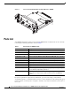
Parts List Cisco Connected Grid Modules for CGR 1000 Series—WiMAX 284549 Figure 1 Parts List Your WiMAX module kit contains one the following WiMAX radio modules. Parts can be ordered by referencing the following information shown in Table 1: Table 1 Kit Contents for WiMAX module Cisco Part Number Description CGM-WIMAX-1.8 WiMAX 1.8 GHz band, subscriber station radio module CGM-WIMAX-2.3 WiMAX 2.
Parts List When using the online publications, see the documents that match the Cisco system software version running on the wireless module.
Features Features Cisco Connected Grid Modules for CGR 1000 Series—WiMAX offers the following key features: Table 2 Feature Information for WiMAX module Feature Description WiMAX technology standard IEEE 802.16e Bands 1.4 GHz band: 1390 to 1510 MGhz (CGM-WIMAX-1.4GHz) 1.8 GHz band: 1800 to 1830 MHz (CGM-WIMAX-1.8GHz) 2.3 GHz bands: 2300 to 2360 MHz (CGM-WIMAX-2.3GHz) 3.65 GHz bands: 3300 to 3800 MHz (CGM-WIMAX-3.
Hardware Overview Table 2 Feature Information for WiMAX module (continued) Feature Description WiMAX IP and Ethernet Convergence Sublayer Allows a WiMAX network to provide Ethernet service directly to customers. Frequency resolution 0.
Hardware Overview • Temperature Monitoring State Machine, page 10 • Module Power States, page 10 Front Panel Figure 2 shows the front panel components of the WiMAX module.
Hardware Overview Supported Cisco WiMAX Antennas The antenna is connected to the QMA, panel-mount, 50-ohm connector located on the faceplate of the module. For more information about antennas, including installation procedures, see Cisco 1240 and 1120 Connected Grid Router Hardware Installation Guide. Table 3 lists the Cisco antennas that are supported for use with the module and the Cisco 1240 Connected Grid Router.
Hardware Overview Table 3 CGR 1240—Supported Antennas and Cables for the WiMAX Module Cisco 1240 Connected Grid Router Case Description Internal Cable Adapter or Lightning Arrestor WiMAX 3.65 GHz external antenna (2) LMR-100, 17.5”, 37-1380-01, CAB-L100-17-Q-M WiMAX 3.65 GHz integrated antenna (2) LMR-100, 17.
Hardware Overview The module provides two physical connectors for antennas. Module States The WiMAX module has the following states: Table 5 WiMAX Module States State Description Configured In this state the WiMAX module has all the necessary configuration information and can be started by the port manager. Modifications to configuration parameters using the configuration file require re-initialization of the WiMAX module.
Hardware Overview Radio Frequency Interface The Radio Frequency (RF) interface consists of two QMA connectors on the faceplate labeled MAIN and AUX. Both antennas are mandatory; it both transmits and receives RF. The second AUX QMA connector is for the optional RX Diversity. DC Power Consumption The average DC power consumption according to the duty cycle is as follows: Table 6 Power Specifications WiMAX 1.
Installing and Removing the WiMAX Module Note • The module unit defaults to the Normal state when VCC is first applied. Disconnected mode—No power to the module. The host power source is disconnected from the module and all voltages associated with the module are at 0 V. CGR 1120 and CGR 1240 controls the power to the module, therefore the host can stay powered on and cut the power in order to put the module into the disconnected state.
Installing and Removing the WiMAX Module Warning To prevent airflow restriction, allow clearance around the ventilation openings to be at least: 1.75 in. (4.4 cm) Statement 1076 Installing the WiMAX Module The WiMAX module can be installed into any slot of the CGR 1240, however Slot 6 is recommended due to the ease of installing the available cable. Note Some WiMAX modules are installed into the host router at the factory.
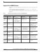
Standards Standards The following standards apply to the Cisco Connected Grid Modules for CGR 1000 Series—WiMAX. Table 7 General Standards Standard Definition IEEE 1613 2009 IEEE Standard for Environmental and Testing Requirements for Communications Networking Devices in Electric Power Substations Regulatory and Compliance Information For regulatory compliance and safety information for the module, refer to the Connected Grid Router 2000 Series Regulatory Compliance and Safety Information document.
Software Overview For more on the WiMAX technology, see the following: http://www.cisco.com/web/about/ac123/ac147/archived_issues/ipj_11-2/112_wimax.html WiMAX Link QoS QoS is configured on the base station. The IEEE standard 802.16e provides the ability to define Quality of Service (QoS) for different data streams. It contains definitions of available parameters and scheduling types. The responsibility of QoS is split between the base station and the mobile stations.
Software Overview Router(config-if)# show interface wimax 4/1 service-flows sfid 8091 Sfid : 8091 CID : 1026 Basic CID : 3 Type : data State : active Direction : Downlink SAID : 65535 Encryption algorithm : None Authentication algorithm : None Scheduling type : Best-effort service Delivery service : best-effort QoS set : Provisioned set Traffic priority : 3 Max rate : 30000000 Max burst : 1000000 Min rate : 0 Max latency : 1000 Tolerated jitter : 1000 Grant interval : 0 Polling Interval : 0 QoS set : Admit
Software Overview QoS Parameters The following are configurable QoS parameters available on the base station: • Traffic priority—This parameter defines the priority assigned to specified service flow. Services with higher traffic priority should be given lower delay and higher buffering preference. However this parameter should not take precedence over any other QoS parameters. The specific algorithm for traffic priorities depends on vendor solution.
Configuring the Module • CS specification—This parameter defines convergence sublayer which should be used for this service flow Additional QoS Commands • (config-scan-list)# nap id nap-id priority priority channel-index channel-index • (config-scan-list)# nsp id nsp-id {home | priority priority channel-index channel-index} Configuring the Module The module is configured using the system software.
Configuring the Module • When a WiMAX module operates in a network with an Airspan base station that has a MAC profile definition based on non-authentication, some of its base station models might require the privacy key management (PKM) to be configured on the WiMAX interface. Updating the base station with the latest firmware generally eliminates the need to change the configuration of the WiMAX module. WiMAX Interface Security The WiMAX module supports the following security methods: • IEEE 802.
Configuring the Module EAP-TLS and EAP-TTLS Authentication Methods To set up a username and password for the Pairwise Key Management (PKM) of a CGR 1000, the WiMAX module must be installed and running. CGR 1000s that ship with a pre-installed WIMAX module will have a pre-installed WiMAX configuration. You can configure your WiMAX interface for one of the following authentication methods: • No Authentication (Open) • EAP-TLS Authentication The WiMAX interface uses trustpoints in the following manner.
Configuring the Module Step 1–WiMAX Scan-list Configuration To create a scan-list, issue the following commands: Router# configure terminal Router(config)# wimax scan-list aaa Router(config-scan-list)# channel index 1 frequency 2350000 bandwidth 10000 Router(config-scan-list)# nap id 00:00:01 priority 1 channel-index 1 Router(config-scan-list)# nsp id 00:00:01 home • NAP (Network Access Provider)—The base station. It provides access to the NSPs which provides network connectivity.
Configuring the Module Note *—The command, pkm trustpoint device device_cert_trustpoint, is not needed if 1) EAP-TLS is using the embedded Airspan certificate, or 2) if EAP-TTLS is used.
Configuring the Module fan mgmt-module module powersupply stby-sup sup xbar Show Show Show Show Show Show Show fan module sprom contents mgmt module (MDS9216/MDS9216i/MDS9222i only) sprom contents linecard module sprom contents powersupply sprom contents stanby supervisor sprom contents supervisor sprom contents xbar fabric sprom contents show interfaces wimax interface_name association The following is an example of the show interfaces wimax interface_name association command: Router # show interface w
Troubleshooting and Diagnostics Initial RNG Backoff Start : 0 Initial RNG Backoff End : 5 Periodic RNG Backoof Start : 0 Periodic RNG Backoff End : 3 Bandwidth Request Backoof Start : 0 Bandwidth Request Backoff End : 3 UL Permutation : 0 UL Subchannel-bitmap : 0xff 0xff 0xff 0xff 0xff 0xff 0xff 0xff Initial-RNG code qty : 4 Periodic-RNG code qty : 4 BWR code qty : 4 DLC CONFIG: bsEirp (dBm) : 4.0 maxRssInitRanging (dBm) : 0.0 PHY: BSiD :0000.000.
Troubleshooting and Diagnostics WiMAX Debug Commands The following are the WiMAX exec debug commands: • clear interface wimax interface name statistics • debug wimax pm {all | demux | deque | error | event | trace | warning} Checking Signal Strength If the Received Signal Strength Indication (RSSI) level is very low (for example, if it is less than -110 dBm), follow these steps: Step 1 Check the antenna connection. Make sure the TNC connector is correctly threaded and tightened.
Troubleshooting and Diagnostics snmpOID : 0.0.0.0.0.0.0.
Additional References • Step 2 Step 3 Step 4 3C9854—Manufacturer’s code Convert manufacturer’s code to decimal as shown: • Hexadecimal 0x60 equals decimal 96. • If the decimal value is two digits only, prepend it with a zero to expand it to three digits. • Manufacturer’s code is thus 096. Convert the serial number to decimal, as shown in the example below: • Hexadecimal 0x3C9854 equals decimal 3971156.
Feature History Cisco System Software Commands Documents • Cisco Connected Grid Device Manager User Guide • Cisco System Software http://www.cisco.com/en/US/products/ps9372/tsd_products_support_series_home.html • Configuring Cisco EHWIC-3G-EDVO-x http://www.cisco.com/en/US/docs/routers/access/1800/1861/software/feature/guide/mrwls_evdo.
Technical Assistance Technical Assistance The Cisco Support and Documentation website provides online resources to download documentation, software, and tools. Use these resources to install and configure the software and to troubleshoot and resolve technical issues with Cisco products and technologies. Access to most tools on the Cisco Support and Documentation website requires a Cisco.com user ID and password. http://www.cisco.com/cisco/web/support/index.