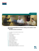
Quick Start Guide Cisco 815 Integrated Services Router Cabling and Installation Quick Start Guide INCLUDING LICENSE AND WARRANTY 1 Cisco 90-Day Limited Hardware Warranty Terms 2 Overview 3 Documents, Equipment, and Tools 4 Ports and LEDs 5 Install the Router 6 Connect to the Router 7 Interface Numbering 8 Power Up the Router 9 Perform Initial Configuration 10 Where to Go Next 11 Obtaining Documentation 12 Documentation Feedback 13 Cisco Product Security Overview 14 Obtaining Technical Ass
Revised November 2007, 78-17436-03 1 Cisco 90-Day Limited Hardware Warranty Terms There are special terms applicable to your hardware warranty and various services that you can use during the warranty period. Your formal Warranty Statement, including the warranties and license agreements applicable to Cisco software, is available on Cisco.com. Follow these steps to access and download the Cisco Information Packet and your warranty and license agreements from Cisco.com. 1.
To Receive a Return Materials Authorization (RMA) Number Contact the company from whom you purchased the product. If you purchased the product directly from Cisco, contact your Cisco Sales and Service Representative.
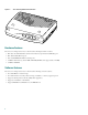
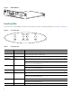
Cisco 815 Integrated Services Router 146794 Figure 1 PWR WIC0 ACT/C WI H0 AC C1 T/CH0 ETH ACT OK ACT/C H1 AC T/C H1 COL Cisco 80 seri0 es r o u te r Hardware Features The Cisco 815 integrated services router has the following hardware features: • One cable modem Data-Over-Cable Service Interface Specification (DOCSIS) port • One 10/100 Fast Ethernet port • Four 10/100BASE-TX Ethernet switch ports • 32 MB of flash memory and 64 MB of DRAM (DRAM can be upgraded to 128 MB) • 32 MB of NVRAM Softw
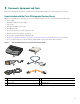
3 Documents, Equipment, and Tools This section describes the documents, equipment, and tools included with the Cisco 815 integrated services router. Items Included with the Cisco 815 Integrated Services Router When you unpack the box containing your Cisco 815 integrated services router, you should find the following items: • Power supply • One DB-9-to-DB-25 modem adapter • Power cable • One RJ-45-to-DB-9 console cable • One Ethernet cable • Cisco.
Items Not Included with the Cisco 815 Integrated Services Router One or more items in this list may be required for your installation: • PC running terminal emulation software, or a modem for remote administrative access • Cable for cable-modem interface • Cable ties • Number-2 Phillips screwdriver User Documentation For complete platform documentation, see the following URL: http://www.cisco.com/en/US/products/hw/routers/ps380/tsd_products_support_series_home.
4 WIC 1 slot 10 10/100-Mbps Fast Ethernet port 5 Power switch 11 FDX, 100, and LINK LEDs 6 Power socket 12 WIC 0 OK LED Table 1 Back Panel Connectors Connector/Slot Label/Color Description Fast Ethernet port 10/100 ETHERNET (yellow) Connects the router to the local Ethernet network through this port. This port autosenses the speed (10 Mbps or 100 Mbps) and duplex mode (full- or half-) of the device to which it is connected and then operates at the same speed and duplex mode.
Figure 5 DS ABLE-D -2 US ONLINE CABLE LINK 146788 HWIC-C HWIC-CABLE-D-2 POWER Front Panel LEDs Use the router front panel LEDs to determine network activity and status on the Ethernet WIC ports. See Figure 6 and Table 3. Front Panel LEDs WIC0 Table 3 WIC1 ETH PWR ACT/CH0 ACT/CH0 ACT OK ACT/CH1 ACT/CH1 COL 65537 Figure 6 Front Panel LEDs LED Label Color Description PWR Green On when DC power is being supplied to the router. OK Green Blinks during the power-on self-test (POST).
Table 3 Front Panel LEDs (continued) LED Label Color Description ACT Green Blinks when there is network activity on the Ethernet port. COL Yellow Blinks when there are packet collisions on the local Ethernet network. 5 Install the Router Set the Cisco 815 integrated services router on a desktop or table. Attach the four rubber feet to the bottom of the chassis.
Warnings and Cautions When you install the Cisco 815 integrated services router, observe the warnings and precautions in this section. In addition, for safety information you must know before working on your Cisco router, see the Regulatory Compliance and Safety Information for Cisco 800 Series and SOHO Series Routers document that accompanied this device. The Regulatory Compliance and Safety Information document also contains translations of the warnings that appear in this quick start guide.
Warnung WICHTIGE SICHERHEITSHINWEISE Dieses Warnsymbol bedeutet Gefahr. Sie befinden sich in einer Situation, die zu Verletzungen führen kann. Machen Sie sich vor der Arbeit mit Geräten mit den Gefahren elektrischer Schaltungen und den üblichen Verfahren zur Vorbeugung vor Unfällen vertraut. Suchen Sie mit der am Ende jeder Warnung angegebenen Anweisungsnummer nach der jeweiligen Übersetzung in den übersetzten Sicherheitshinweisen, die zusammen mit diesem Gerät ausgeliefert wurden.
Aviso INSTRUÇÕES IMPORTANTES DE SEGURANÇA Este símbolo de aviso significa perigo. Você se encontra em uma situação em que há risco de lesões corporais. Antes de trabalhar com qualquer equipamento, esteja ciente dos riscos que envolvem os circuitos elétricos e familiarize-se com as práticas padrão de prevenção de acidentes. Use o número da declaração fornecido ao final de cada aviso para localizar sua tradução nos avisos de segurança traduzidos que acompanham o dispositivo.
Warning Before working on a system that has an on/off switch, turn OFF the power and unplug the power cord. Statement 1 Warning Ultimate disposal of this product should be handled according to all national laws and regulations. Statement 1040 Warning To prevent the system from overheating, do not operate it in an area that exceeds the maximum recommended ambient temperature of 40 deg.
Warning Do not work on the system or connect or disconnect cables during periods of lightning activity. Statement 1001 Warning Read the installation instructions before connecting the system to the power source. Statement 1004 Note The installation must comply with all required electrical codes applicable at the installation site. Cable Connections Warning Note Hazardous network voltages are present in WAN ports regardless of whether power to the router is OFF or ON.
Figure 7 Connecting the Console Cable to the Router 4 WIC 4ESW Cisco 815 ACT 4x LN K ACT 3x LNK ACT 2x LN K WIC0O ACT 1x LN K CONS OLE K FDX 100 LINK 10/100 ETHE HWICCABL E-D-2 RNET AUX DS CABL US ONLIN E E MOD OK W LINK POWE R IC 1O K +5, +1 1 2, -1 2 VD C 2 146793 3 1 Console cable 3 To PC or terminal 2 Console port 4 Cisco 815 integrated services router Step 3 Connect the DB-9 end of the console cable to the serial port on your PC.
8 Power Up the Router This section provides the procedures for powering up your Cisco 815 integrated services router. Caution To ensure adequate cooling, never operate the router unless the cover and all WICs and cover plates are installed. Checklist for Power-Up You are ready to power up the Cisco 815 integrated services router after the following steps are completed: • Chassis is securely mounted and grounded. (See the “Install the Router” section on page 9.) • Power and interface cables are connected.
Note Because Cisco SDM is installed on your router by default, we recommend using Cisco SDM to perform the initial configuration. See the “Configure the Router Using Cisco Router and Security Device Manager” section on page 19 to learn how to configure your router using Cisco SDM, or how to obtain Cisco SDM and install it on your router.
Setting Up the Initial Configuration Using the Setup Command Facility This section shows how to use the setup command facility to configure a hostname for the Cisco 815 integrated services router, to set passwords, and to configure an interface for communication with the management network. If the following messages appear at the end of the startup sequence, the setup command facility has been invoked automatically: --- System Configuration Dialog --At any point you may enter a question mark '?' for help.
enable secret password, with some older software versions, and some boot images. Enter enable password: xxxxxx Step 6 Enter the virtual terminal password, which prevents unauthenticated access to the Cisco 815 integrated services router through ports other than the console port: The virtual terminal password is used to protect access to the router over a network interface.
[1] Return back to the setup without saving this config. [2] Save this configuration to nvram and exit. Enter your selection [2]: 2 Building configuration... Use the enabled mode 'configure' command to modify this configuration.
11 Obtaining Documentation Cisco documentation and additional literature are available on Cisco.com. Cisco also provides several ways to obtain technical assistance and other technical resources. These sections explain how to obtain technical information from Cisco Systems. Cisco.com You can access the most current Cisco documentation at this URL: http://www.cisco.com/techsupport You can access the Cisco website at this URL: http://www.cisco.
13 Cisco Product Security Overview Cisco provides a free online Security Vulnerability Policy portal at this URL: http://www.cisco.com/en/US/products/products_security_vulnerability_policy.html From this site, you will find information about how to: • Report security vulnerabilities in Cisco products. • Obtain assistance with security incidents that involve Cisco products. • Register to receive security information from Cisco.
Cisco Technical Support & Documentation Website The Cisco Technical Support & Documentation website provides online documents and tools for troubleshooting and resolving technical issues with Cisco products and technologies. The website is available 24 hours a day, at this URL: http://www.cisco.com/techsupport Access to all tools on the Cisco Technical Support & Documentation website requires a Cisco.com user ID and password.
15 Obtaining Additional Publications and Information Information about Cisco products, technologies, and network solutions is available from various online and printed sources. • The Cisco Product Quick Reference Guide is a handy, compact reference tool that includes brief product overviews, key features, sample part numbers, and abbreviated technical specifications for many Cisco products that are sold through channel partners. It is updated twice a year and includes the latest Cisco offerings.
Corporate Headquarters Cisco Systems, Inc. 170 West Tasman Drive San Jose, CA 95134-1706 USA www.cisco.com Tel: 408 526-4000 800 553-NETS (6387) Fax: 408 526-4100 European Headquarters Cisco Systems International BV Haarlerbergpark Haarlerbergweg 13-19 1101 CH Amsterdam The Netherlands www-europe.cisco.com Tel: 31 0 20 357 1000 Fax: 31 0 20 357 1100 Americas Headquarters Cisco Systems, Inc. 170 West Tasman Drive San Jose, CA 95134-1706 USA www.cisco.