GETTING STARTED GUIDE Cisco Aironet 700 Series Access Points June 2013 1 About this Guide 2 Introduction to the Access Point 3 Safety Instructions 4 Unpacking 5 Configurations 6 Access Point Ports and Connectors 7 Configuring the Access Point 8 Mounting the Access Point 9 Deploying the Access Point on the Wireless Network 10 Troubleshooting 11 Declarations of Conformity and Regulatory Information 12 Configuring DHCP Option 43 and DHCP Option 60 13 Access Point Specifications
1 About this Guide This Guide provides instructions on how to install and configure your Cisco Aironet 700 Series Access Point. The 700 Series Access Point is referred to as the 700 series or the access point in this document. 2 Introduction to the Access Point The 700 series supports high-performing two spatial stream rates over a deployable distance with high reliability when serving clients. The 700 series provides high reliability and overall wireless performance.
Warning IMPORTANT SAFETY INSTRUCTIONS This warning symbol means danger. You are in a situation that could cause bodily injury. Before you work on any equipment, be aware of the hazards involved with electrical circuitry and be familiar with standard practices for preventing accidents. Use the statement number provided at the end of each warning to locate its translation in the translated safety warnings that accompanied this device.
Unpacking To unpack the access point, follow these steps: Step 1 Unpack and remove the access point and the accessory kit from the shipping box. Step 2 Return any packing material to the shipping container and save it for future use. Step 3 Verify that you have received the items listed below. If any item is missing or damaged, contact your Cisco representative or reseller for instructions.
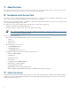
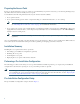
Figure 1 Access Point LED Indicator (top) 347756 1 1 LED indicator The ports and connections on the side of the access point are shown in Figure 2.
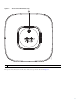
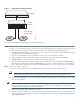
Figure 2 Access Point Ports and Connections (bottom) 2 3 4 347755 1 5 6 5 1 Mode button 4 AC power connector 2 Ethernet port 5 Mounting bracket pins 3 Console port 6 Security hasp 7 Configuring the Access Point This section describes how to connect the access point to a wireless LAN controller. Because the configuration process takes place on the controller, see the Cisco Wireless LAN Controller Configuration Guide for additional information. This guide is available on Cisco.com.
The Controller Discovery Process The access point uses standard Control and Provisioning of Wireless Access Points Protocol (CAPWAP) to communicate between the controller and other wireless access points on the network. CAPWAP is a standard, interoperable protocol which enables an access controller to manage a collection of wireless termination points. The discovery process using CAPWAP is identical to the Lightweight Access Point Protocol (LWAPP) used with previous Cisco Aironet access points.
Preparing the Access Point Before you mount and deploy your access point, we recommend that you perform a site survey (or use the site planning tool) to determine the best location to install your access point. You should have the following information about your wireless network available: • Access point locations. • Access point mounting options: below a suspended ceiling, on a flat horizontal surface, or on a desktop.
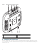
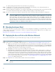
Figure 3 Pre-Installation Configuration Setup Controller Layer 3 devices 272488 Cisco Aironet access points To perform pre-installation configuration, perform the following steps: Step 1 Make sure that the Cisco wireless LAN controller DS port is connected to the network. Use the CLI, web-browser interface, or Cisco Prime Infrastructure procedures as described in the appropriate Cisco wireless LAN controller guide. a.
e. If the operating system download is successful, the access point reboots. Step 3 Configure the access point if required. Use the controller CLI, controller GUI, or Cisco Prime Infrastructure to customize the access-point-specific 802.11n network settings. Step 4 If the pre-installation configuration is successful, the Status LED is green indicating normal operation. Disconnect the access point and mount it at the location at which you intend to deploy it on the wireless network.
10 Troubleshooting If you experience difficulty getting your access point installed and running, look for a solution to your problem in this guide or in additional access point documentation. These, and other documents, are available on Cisco.com.
Table 1 LED Status Indications (continued) Message Type Status LED Message Meaning Operating status Blinking amber Software upgrade in progress Cycling through green, red, and amber Discovery/join process in progress Rapidly cycling Access point location command invoked through red, green, and amber Boot loader warnings Boot loader errors Blinking red Ethernet link not operational Blinking amber Configuration recovery in progress (MODE button pushed for 2 to 3 seconds) Red Ethernet failure
An access point sends all syslog messages to IP address 255.255.255.255 by default when any of the following conditions are met: • An access point running software release 5.2 or later has been newly deployed. • An existing access point running software release 5.2 or later has been reset after clearing the configuration.
Manufacturer: Cisco Systems, Inc. 170 West Tasman Drive San Jose, CA 95134-1706 USA This device complies with Part 15 rules. Operation is subject to the following two conditions: 1. This device may not cause harmful interference, and 2. This device must accept any interference received, including interference that may cause undesired operation. This device operates in the 5150-5250MHz and 5470-5725MHz bands and is therefore restricted to indoor operation only per FCC guidance.
Guidelines for Operating Cisco Aironet Access Points in Japan This section provides guidelines for avoiding interference when operating Cisco Aironet access points in Japan. These guidelines are provided in both Japanese and English.
English Translation When installing the product, please use the provided or designated connection cables/power cables/AC adaptors. Using any other cables/adaptors could cause a malfunction or a fire. Electrical Appliance and Material Safety Law prohibits the use of UL-certified cables (that have the “UL” shown on the code) for any other electrical devices than products designated by CISCO.
European Community, Switzerland, Norway, Iceland, and Liechtenstein Models: AIR-CAP702I-E-K9 AIR-SAP702I-E-K9 Declaration of Conformity with regard to the R&TTE Directive 1999/5/EC & Medical Directive 93/42/EEC 17
The following standards were applied: EMC—EN 301.489-1 v1.8.1; EN 301.489-17 v2.1.1 Health & Safety—EN60950-1: 2005; EN 50385: 2002 Radio—EN 300 328 v 1.7.1; EN 301.893 v 1.5.1 The conformity assessment procedure referred to in Article 10.4 and Annex III of Directive 1999/5/EC has been followed. This device also conforms to the EMC requirements of the Medical Devices Directive 93/42/EEC. Note This equipment is intended to be used in all EU and EFTA countries.
Generic Discussion on RF Exposure The Cisco products are designed to comply with the following national and international standards on Human Exposure to Radio Frequencies: • US 47 Code of Federal Regulations Part 2 Subpart J • American National Standards Institute (ANSI) / Institute of Electrical and Electronic Engineers / IEEE C 95.1 (99) • International Commission on Non Ionizing Radiation Protection (ICNIRP) 98 • Ministry of Health (Canada) Safety Code 6.
This Device Meets the Industry Canada Guidelines for Exposure to Radio Waves The 700 series device includes a radio transmitter and receiver. It is designed not to exceed the limits for exposure to radio waves (radio frequency electromagnetic fields) as referenced in Health Canada Safety Code 6. The guidelines include a substantial safety margin designed into the limit to ensure the safety of all persons, regardless of age and health.
Chinese Translation English Translation Administrative Rules for Low-power Radio-Frequency Devices Article 12 For those low-power radio-frequency devices that have already received a type-approval, companies, business units or users should not change its frequencies, increase its power or change its original features and functions.
Chinese Translation English Translation Low-power Radio-frequency Devices Technical Specifications 4.7 Unlicensed National Information Infrastructure 4.7.5 Within the 5.25-5.35 GHz band, U-NII devices will be restricted to indoor operations to reduce any potential for harmful interference to co-channel MSS operations. 4.7.6 The U-NII devices shall accept any interference from legal communications and shall not interfere the legal communications.
Operation of Cisco Aironet Access Points in Brazil This section contains special information for operation of Cisco Aironet access points in Brazil. Access Point Models AIR-CAP702I-T-K9 AIR-SAP702I-T-K9 Portuguese Translation Este equipamento opera em caráter secundário, isto é, não tem direito a proteção contra interferência prejudicial, mesmo de estações do mesmo tipo, e não pode causar interferência a sistemas operando em caráter primário.
Step 2 Create the DHCP pool, including the necessary parameters such as default router and name server. A DHCP scope example is as follows: ip dhcp pool network default-router dns-server Where: is the name of the DHCP pool, such as AP702 is the network IP address where the controller resides, such as 10.0.15.1 is the subnet mask, such as 255.255.255.
Table 2 Access Point Specifications (continued) Category Specification Safety UL 60950-1 CAN/CSA C22.2 No. 60950-1 IEC 60950-1 with all national deviations EN 60950-1 UL 2043 EMI and Susceptibility FCC Part 15.107 and 15.109 Class B ICES-003 Class B (Canada) EN 301.489 EN 55022 Class B EN 55024 VCCI Class B Radio FCC Part 15.247, 15.407 Canada RSS-210 Japan Telec 33, 66, T71 EN 330.328, EN 301.
Cisco and the Cisco logo are trademarks or registered trademarks of Cisco and/or its affiliates in the U.S. and other countries. To view a list of Cisco trademarks, go to this URL: www.cisco.com/go/trademarks. Third-party trademarks mentioned are the property of their respective owners. The use of the word partner does not imply a partnership relationship between Cisco and any other company. (1110R) Any Internet Protocol (IP) addresses used in this document are not intended to be actual addresses.