
- Cisco 5700 Series Wireless Controller Manual


25
Cisco 5700 Series Wireless Controller Installation Guide
OL-28544-01
Power Supply Installation
Step 2 Enter show port summary. The following information appears, showing the status of the controller’s
distribution system ports, which serve as the data path between the controller and Cisco lightweight
access points and to which the controller’s management interface is mapped.
STP Admin Physical Physical Link Link Mcast
Pr Type Stat Mode Mode Status Status Trap Appliance POE
-- ------- ---- ------- ---------- ---------- ------ ------- --------- -------
1 Normal Forw Enable Auto 1000 Full Up Enable Enable N/A
2 Normal Forw Enable Auto 1000 Full Up Enable Enable N/A
A link status of Up indicates that the controller’s ports are fully operational.
Connecting the Console Port (Optional)
The console port is controlled by the console-port interface and is reserved for out-of-band management
of the controller and system recovery and maintenance in the event of a network failure. The
console-port interface enables the controller to be managed on an interface different from the one used
for your network traffic. Use of the console port is optional.
You can perform out-of-band controller management from a PC running a terminal emulation program
or a PC running Cisco Prime infrastructure, a network management tool that enables you to configure
and monitor a network of controllers, or the controller GUI. However, you must first connect the PC to
the switch’s console port in one of two ways:
• Use an Ethernet cross-over cable to connect the PC directly to the switch’s console port.
• For a remote connection (using Telnet or SSH) through a dedicated management network, use a
Category 5, Category 5e, Category 6, or Category 7 Ethernet cable to connect the management
network to the controller’s console port and the appropriate cable to connect the PC to the
management network.
Connecting Access Points
After you have configured the controller, use Category-5, Category-5e, Category-6, or Category-7
Ethernet cables to connect Cisco lightweight access points to the network.
As soon as the controller is operational, it starts to scan for access points. When it detects an access point,
it records the access-point MAC address in its database. The controller Radio Resource Management
(RRM) feature then automatically configures the access point to start sending and allowing clients to
associate.
You have prepared the controller for basic operation. Refer to the Cisco Wireless LAN Controller
Configuration Guide, Release 6.0, for information on configuring the controller to meet the specific
needs of your wireless network.
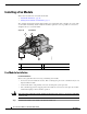
Power Supply Installation
The controller can be powered using one or two power supply units. When the controller is equipped
with two power supply units, the power supplies are redundant. Either power supply continues to power
the controller should the other power supply unit fail. Also, the power supplies are hot swappable; you
do not need to remove power from the controller to replace a power supply.