Cisco 5700 Series Wireless Controller Installation Guide This guide is designed to help you install and minimally configure your Cisco 5700 Series Wireless Controller.
Compliance and Safety Information This equipment has been tested and found to comply with the limits for a Class A digital device, pursuant to Part 15 of the FCC Rules. These limits are designed to provide reasonable protection against harmful interference when the equipment is operated in a commercial environment.
Controller Overview Statement 191—VCCI Class A Warning for Japan Warning This is a Class A product based on the standard of the VCCI Council. If this equipment is used in a domestic environment, radio interference may occur, in which case, the user may be required to take corrective actions. VCCI-A Controller Overview The Cisco 5700 Series Wireless Controller, designed for 802.
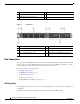
Controller Overview 1 Mode button 4 USB port (Type A) 2 System LEDs 5 1/10G SFP+ ports 3 USB mini-Type B (console) port Figure 2 Back Panel 1 Console (RJ-45 console port) 5 AC OK (input) status LED 2 StackWise port 6 PS OK (output) status LED 3 Fan FRU modules 7 Redundant FRU power supplies 4 Ground lug mounting location 8 MGMT (RJ-45 10/100/1000 management port) Port Connections The controller has both EIA/TIA-232 asynchronous (RJ-45) and USB 5-pin mini Type B, 2.
Controller Overview Cisco IOS software provides standard file system access to the flash device: read, write, erase, and copy, as well as the ability to format the flash device with a FAT file system. USB Mini-B Console Port The controller provides a USB mini-Type B console connection on the front panel, and an RJ-45 console port on the rear panel.
Controller Overview 1/10G SFP+ Ports The SFP and SFP+ modules provide copper or fiber-optic connections to other devices. These transceiver modules are field-replaceable, providing the physical interfaces when installed in an SFP module slot. The SFP modules have LC connectors for fiber-optic connections or RJ-45 connectors for copper connections. Use only Cisco SFP and SFP+ modules on the controller. Warning Class 1 laser product. Statement 1008 1/10G SFP+ port LED meanings: • Off—The link is down.
Controller Overview Table 1 Supported Cisco SFP Modules (continued) Part Number Description CWDM-SFP-1590= CWDM 1590-nm SFP Gigabit Ethernet and 1G/2G FC CWDM-SFP-1610= CWDM 1610-nm SFP Gigabit Ethernet and 1G/2G FC SFP-GE-S= 1000BASE-SX SFP module for MMF, 850 nm (DOM) SFP-GE-L= 1000BASE-LX/LH SFP module for SMF, 1300 nm (DOM) DWDM-SFP-3033= DWDM SFP 1530.33-nm SFP (100 GHz ITU grid) DWDM-SFP-3112= DWDM SFP 1531.12-nm SFP (100 GHz ITU grid) DWDM-SFP-3190= DWDM SFP 1531.
Controller Overview Table 1 Supported Cisco SFP Modules (continued) Part Number Description DWDM-SFP-5575= DWDM SFP 1555.75-nm SFP (100 GHz ITU grid) DWDM-SFP-5655= DWDM SFP 1556.55-nm SFP (100 GHz ITU grid) DWDM-SFP-5736= DWDM SFP 1557.36-nm SFP (100 GHz ITU grid) DWDM-SFP-5817= DWDM SFP 1558.17-nm SFP (100 GHz ITU grid) DWDM-SFP-5898= DWDM SFP 1558.98-nm SFP (100 GHz ITU grid) DWDM-SFP-5979= DWDM SFP 1559.79-nm SFP (100 GHz ITU grid) DWDM-SFP-6061= DWDM SFP 1560.
Controller Overview RJ-45 Console Port The RJ-45 console port connection uses an RJ-45-to-DB-9 female cable. Console port LED meanings: • Off—The RJ-45 console is inactive (the USB console is active). • Green—The RJ-45 console is active (the USB console is inactive). 10/100/1000 Ethernet Management Port You can connect the controller to a host such as a Windows workstation or a terminal server through the 10/100/1000 Ethernet management port.
Unpacking and Installing the Controller Table 3 Mode LED Indicators (continued) Mode LED Description SYST (system) Off—The system is off. Green—The system is operating normally. Blinking green—The system is running POST. Amber—The system is malfunctioning. Blinking amber—The power supply or fan module is malfunctioning. ACTV (active) Off—The switch is not the active switch. Green—The switch is the active switch or is in standalone mode. Blinking green—The switch is in standby mode.
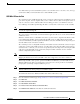
Unpacking and Installing the Controller Box Contents 1 2 ACTV Cisc o 57 00 Se ries Wire less Cont rolle r 6 Mod el 57 60 7 10 8 12 9 5 4 13 14 11 345939 3 1 Cisco 5700 Series Wireless Controller (power supply and fan modules not shown)1 8 Four number-10 pan-head screws 2 AC power cord 9 Eight number-8 Phillips flat-head screws 3 Four rubber mounting feet 10 Cable guide 4 Ground lug ring terminal 11 M4.
Unpacking and Installing the Controller – VT-100 terminal emulator on CLI console (PC, laptop, or palmtop) – Null modem serial cable to connect CLI console and controller • Local TFTP server (required for downloading operating system software updates). Cisco uses an integral TFTP server. This means that third-party TFTP servers cannot run on the same workstation as Cisco Prime Infrastructure because Cisco Prime Infrastructure and third-party TFTP servers use the same communication port.
Unpacking and Installing the Controller Warning To prevent airflow restriction, allow clearance around the ventilation openings to be at least: 4 in (10.16 cm) Statement 1076 • Make sure you can reach the controller and all cables attached to it. • Make sure that water or excessive moisture cannot get into the controller. • Make sure that the SFP and SFP+ Module Cable Specifications are met.
Unpacking and Installing the Controller Table 4 Fiber-Optic SFP and SFP+ Module Port Cabling Specifications (continued) Core Size/Cladding Size (micron) Modal Bandwidth (MHz/km)1 SFP Module Wavelength (nanometers) Cable Type Cable Distance SFP-GE-L 1300 MMF or SMF 62.5 50 50 9/10 500 400 500 1804 feet (550 m) 1804 feet (550 m) 1804 feet (550 m) 6.2 miles (10 km) SFP-GE-S 850 MMF 62.5 62.
Unpacking and Installing the Controller Table 4 Fiber-Optic SFP and SFP+ Module Port Cabling Specifications (continued) Core Size/Cladding Size (micron) SFP Module Wavelength (nanometers) Cable Type 10GBASE-CX1 — Twinax cable, — 30-AWG cable assembly (SFP-H10GB-CU1M) (SFP-H10GB-CU3M) (SFP-H10GB-CU5M) Modal Bandwidth (MHz/km)1 Cable Distance — 3 feet (1 m) Twinax cable, 30-AWG cable assembly 9 feet (3 m) Twinax cable, 24-AWG cable assembly 16 feet (5 m) 1.
Unpacking and Installing the Controller Warning To prevent bodily injury when mounting or servicing this unit in a rack, you must take special precautions to ensure that the system remains stable. The following guidelines are provided to ensure your safety: • This unit should be mounted at the bottom of the rack if it is the only unit in the rack. • When mounting this unit in a partially filled rack, load the rack from the bottom to the top with the heaviest component at the bottom of the rack.
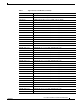
Unpacking and Installing the Controller 1 19-inch brackets (C3850-RAC-KIT=) 4 23-inch brackets (C3850-RAC-KIT=) 2 Extension rails and brackets for four-point mounting, includes 19-inch brackets. (C3850-4PT-KIT=) 5 24-inch brackets (C3850-RAC-KIT=) 3 ETSI brackets (C3850-RAC-KIT=) Attaching the Rack-Mount Brackets To install the controller in a rack, use four Phillips flat-head screws to attach the long side of the brackets to the controller for the front- or rear-mounting positions (Figure 4).
Unpacking and Installing the Controller Figure 4 Attaching Brackets for 19-inch Racks 1 2 2 3 es W irele ss Con troll er Mod el 5 760 2 2 3 2 Con troll er Mod 2 el 5 760 2 2 1 Rear-mounting position 2 Number-8 Phillips flat-head screws 3 Front-mounting position 345727 es W irele ss Cisco 5700 Series Wireless Controller Installation Guide 18 OL-28544-01
Unpacking and Installing the Controller Mounting the Controller in a Rack After the brackets are attached to the controller, use the supplied Phillips machine screws to attach the brackets to the rack (Figure 5). Use the black Phillips machine screw to attach the cable guide to the left or right bracket.
Unpacking and Installing the Controller Grounding the Chassis Follow the grounding procedures at your site and observe these warnings: Warning This equipment must be grounded. Never defeat the ground conductor or operate the equipment in the absence of a suitably installed ground conductor. Contact the appropriate electrical inspection authority or an electrician if you are uncertain that suitable grounding is available.
Unpacking and Installing the Controller Step 5 Step 6 Install the ground lug: a. Remove the first hex nut from the bracket and place the ground lug over the screw threads. b. Place the hex nut back on the screw threads and tighten. Reinstall the ground bracket onto the controller. Figure 8 Step 7 Ground Bracket Prepare the other end of the grounding cable and connect it to an appropriate grounding point in your site to ensure adequate earth ground.
Using the Startup Wizard Note You can use either the RJ-45 console port or the USB console port. Note The first time that you connect a Windows PC to the USB console port, you are prompted to install the USB console driver. Follow the installation prompts to install the driver. The USB console driver maps to a COM port on your PC; you then need to map the terminal emulator application to the COM port. See the “USB Mini-B Console Port” section on page 5 for more information about the USB console driver.
Using the Startup Wizard Step 3 Enter the enable secret password. This password is used to protect access to privileged EXEC and configuration modes. This password, after entered, becomes encrypted. Step 4 Enter the enable password. This password is used when you do not specify an enable secret password (for some older software versions, and some boot images). Step 5 Enter the virtual terminal password. This password is used to protect access to the controller over a network interface.
Using the Startup Wizard Step 13 When prompted to verify that the configuration is correct, enter one of the following: • 0—Go to the IOS command prompt without saving this config. • 1—Return back to the setup without saving this config. • 2—Save this configuration to nvram and exit. Logging into the Controller Follow these steps to log into the controller: Step 1 Enter a valid username and password to log into the controller CLI.
Power Supply Installation Step 2 Enter show port summary. The following information appears, showing the status of the controller’s distribution system ports, which serve as the data path between the controller and Cisco lightweight access points and to which the controller’s management interface is mapped.
Power Supply Installation One power supply unit is installed in slot 1 at the factory. You can order a second power supply unit and install it in slot 2. The power supplies do not have an on/off switch and can only be powered down by removing AC input. Note If only one power supply will be used, you must use the supplied blank faceplate to cover the empty power slot. Power Supply Module Overview All power supply modules have internal fans.
Power Supply Installation Figure 10 Power Supply Slot Cover 253564 2 1 1 Release handles 2 Retainer clips Table 6 describes the power supply modules status LEDs. Table 6 Power Supply Module LEDs AC Power Supply Module LEDs AC OK Description PS OK Description Off (AC LED is off) No AC input power. Off Output is disabled, or input is outside operating range. Green AC input power present. Green Power output to the controller. Red Output has failed.
Power Supply Installation Warning Installation of the equipment must comply with local and national electrical codes. Statement 1074 Warning Do not reach into a vacant slot when installing or removing a module. Exposed circuitry is an energy hazard. Statement 206 Warning Only trained and qualified personnel should be allowed to install, replace, or service this equipment. Statement 1030 Installing or Replacing an AC Power Supply Step 1 Turn off the power at its source.
Power Supply Installation Figure 12 AC-Power Supply with Power Cord Retainer PS OK -715WAC PWR-C1 AC OK PS OK -715WAC PWR-C1 345730 AC OK Step 7 Connect the power cord to the power supply and to an AC power outlet. Turn on the power at the power source. Step 8 Confirm that the power supply AC OK and PS OK LEDs are green. Finding the Power Supply Module Serial Number If you contact Cisco Technical Assistance regarding a power supply module, you need to know the serial number.
Installing a Fan Module Installing a Fan Module This section describes how to install a fan module. • Fan Module Installation, page 30 • Finding the Fan Module Serial Number, page 31 The controller has four fan modules. Fan modules are hot-swappable. The controller can operate with one fan failure indefinitely, but the faulty fan should be replaced as soon as possible to avoid service disruption due to a second fan failure.
Installing a Fan Module Caution You should replace the fan module within 5 minutes to avoid overheating the controller. Step 2 Install the fan module in the fan slot, and firmly push it into the slot, applying pressure to the end of the module, not the extraction handles. When correctly inserted, the fan module is flush with the controller rear panel. When the fan is operating, a green LED is on in the top left corner of the fan. See Figure 15.
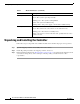
Specifications Fan Module Serial Number 334328,781-00761-01 Figure 16 SN: XXXNNNNXXXX Specifications Table 7 through Table 9 list the specifications for the controller and its power supply and fan modules.
Cisco 90-Day Limited Hardware Warranty Terms Table 8 Environmental and Physical specifications for the Power Supply Module (continued) Physical Specifications Weight PWR-C1-350WAC 2.6 lb (1.2 kg) Dimensions (H x D x W) PWR-C1-350WAC 1.58 x 10.22 x 3.25 in. (4 x 26 x 8.3 cm) Note Table 9 Dimensions shown exclude the extraction handle, which measures 1.55 in (3.9 cm) and the keying feature which measures 0.44 in (1.1 cm).
Obtaining Documentation and Submitting a Service Request Note 3. You must have Adobe Acrobat Reader to view and print PDF files. You can download the reader from Adobe’s website: http://www.adobe.com To read translated and localized warranty information about your product, follow these steps: a. Enter this part number in the Warranty Document Number field: 78-5236-01C0 b. Select the language in which you would like to read the document. c. Click Go. The Cisco warranty page appears. d.
Related Documentation Subscribe to the What’s New in Cisco Product Documentation as a Really Simple Syndication (RSS) feed and set content to be delivered directly to your desktop using a reader application. The RSS feeds are a free service and Cisco currently supports RSS Version 2.0. Related Documentation Before installing or upgrading the controller, refer to the controller release notes. • Cisco 5700 Series Wireless Controller documentation at: http://www.cisco.
Related Documentation Cisco 5700 Series Wireless Controller Installation Guide 36 OL-28544-01