
- Cisco 4451-X Integrated Services Router Manual
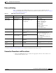
Table Of Contents
- Hardware Installation Guide for the Cisco 4451-X Integrated Services Router
- Contents
- Preface
- Overview of the Cisco 4451-X Integrated Services Router
- About the Cisco ISR 4451-X
- Safety Warnings
- Safety Warnings for Finland, Norway and Sweden
- Chassis Views
- Cisco ISR 4451-X Chassis
- Platform Summary
- Locating the Serial Number, PID, VID and CLEI
- Labels on Cisco ISR 4451-X
- For Additional Help Locating Labels on the Router
- Hardware Features
- Built-in Interface Ports
- Front Panel Ethernet Ports
- Dual Mode GE/SFP Ports
- USB Serial Console Port
- Front Panel PoE+ Ports
- Internal PoE card
- LED Indicators
- Removable and Interchangeable Modules and Cards
- Network Interface Modules
- Cisco UCS E-Series Server Modules
- Compact Flash
- Solid State Drives
- Packet Voice Digital Signal Processor Modules
- Memory
- Power Supplies
- Fans, Ventilation, and Airflow
- About Slots and Interfaces
- About Slot, Subslot (Bay), and Port Numbering
- Slot Numbering
- About Slot 0
- About Slot 1 and 2
- Additional Slots
- Subslot/Bay Numbering
- Gigabit Ethernet Management
- About Fixed Interfaces
- Specifications
- Periodic Inspection and Cleaning
- Preparing for Router Installation
- Standard Warning Statements
- General Safety Warnings
- Safety Recommendations
- Safety with Electricity
- Preventing Electrostatic Discharge Damage
- General Site Requirements
- General Precautions
- Site Selection Guidelines
- Site Environmental Requirements
- Physical Characteristics
- Rack Requirements
- Router Environmental Requirements
- Power Guidelines and Requirements
- Network Cabling Specifications
- Console and Auxiliary Port Considerations
- Console Port Connections
- Auxiliary Port Connections
- Preparing for Network Connections
- Ethernet Connections
- Required Tools and Equipment for Installation and Maintenance
- Installation Checklist
- Creating a Site Log
- Installing and Connecting the Router
- What You Need to Know
- Before You Begin
- Unpacking the Router
- Installing the Router
- Rack-Mounting the Chassis
- Attaching Rack-Mount Brackets
- Mounting the Router in a Rack
- Grounding the Chassis
- Setting the Chassis on a Desktop
- Chassis Grounding
- Connecting Power
- Connecting to AC Power
- Connecting to a Console Terminal or Modem
- Connecting to the Serial Port with Microsoft Windows
- Connecting to the Console Port with Mac OS X
- Connecting to the Console Port with Linux
- Installing the Cisco Microsoft Windows USB Device Driver
- Installing the Cisco Microsoft Windows XP USB Driver
- Installing the Cisco Microsoft Windows 2000 USB Driver
- Installing the Cisco Microsoft Windows Vista USB Driver
- Uninstalling the Cisco Microsoft Windows USB Driver
- Uninstalling the Cisco Microsoft Windows XP and 2000 USB Driver
- Uninstalling the Cisco Microsoft Windows Vista USB Driver
- Connecting to the Auxiliary Port
- Connecting WAN, LAN, and Voice Interfaces
- Ports and Cabling
- Connection Procedures and Precautions
- Initial Configuration
- Performing the Initial Configuration on the Router
- Using Cisco Setup Command Facility
- Completing the Configuration
- Using Cisco IOS-XE CLI-Manual Configuration
- Configuring the Router Hostname
- Configuring the Enable and Enable Secret Passwords
- Configuring the Console Idle Privileged EXEC Timeout
- Gigabit Ethernet Management Interface Overview
- Default Gigabit Ethernet Configuration
- Gigabit Ethernet Port Numbering
- Configuring Gigabit Ethernet Interfaces
- Configuration Examples
- Specifying a Default Route or Gateway of Last Resort
- Configuring IP Routing and IP Protocols
- Default Routes
- Default Network
- Gateway of Last Resort
- Configuration Examples
- Configuring Virtual Terminal Lines for Remote Console Access
- Configuration Examples
- Configuring the Auxiliary Line
- Verifying Network Connectivity
- Saving Your Router Configuration
- Saving Backup Copies of Configuration and System Image
- Configuration Examples
- Verifying the Initial Configuration
- ROM Monitor Overview and Basic Procedures
- ROM Monitor Overview
- Entering ROM Monitor Mode
- Checking the Current ROMmon Version
- Commonly Used ROM Monitor Commands
- Displaying the Available ROM Monitor Commands
- Examples
- Changing the ROM Monitor Prompt
- Displaying the Configuration Register Setting
- Environment Variable Settings
- Frequently Used Environmental Variables
- Displaying Environment Variable Settings
- Entering Environment Variable Settings
- Saving Environment Variable Settings
- Exiting ROM Monitor Mode
- Configuration Example
- Upgrading the ROMmon for a Router
- Example of Upgrade
- Installing and Upgrading Internal Modules and FRUs
- Safety Warnings
- Accessing Internal Modules
- Removing and Replacing the Chassis Cover
- Removing the Cover
- Replacing the Cover
- Locating Internal and External Slots for Modules
- Overview of the SSD Carrier Card NIM (NIM-SSD)
- Overview
- LEDs on the NIM-SSD
- Solid State Drives (SSD)
- Installing the SSD Drives into the NIM Carrier Card
- Removing the SSD Drives from the NIM-SSD
- Removing and Replacing the Cisco ISR 4451-X NIM-SSD Drives
- Removing the NIM-SSD from the Router
- Replacing the NIM-SSD on the Router
- Installing and Removing DDR DIMMs
- Locating and Orienting DIMM
- Removing a DIMM
- Installing a DIMM
- Installing and Removing NIMs and SMs
- Software Requirement for SMs
- Locating an SM or NIM
- Removing an SM or NIM
- Installing an SM
- Verifying SM Installation
- Installing and Removing the PVDM4
- Tools and Equipment Required During Installation
- PVDM4 Location and Orientation
- Installing the PVDM4 on the Motherboard of the Cisco ISR 4451-X
- Removing the PVDM4 from the Motherboard of the Cisco ISR 4451-X
- Installing the PVDM4 on the Cisco Fourth-Generation T1/E1 Voice and WAN NIM in the Cisco ISR 4451-X
- Removing the PVDM4 from the Cisco Fourth-Generation T1/E1 Voice and WAN Network Interface Module in the Cisco ISR 4451-X
- Removing and Replacing the USB Flash Token Memory Stick
- Replacing Power Supplies and Redundant Power Supplies
- Replacing the Cisco ISR 4451-X Power Supply
- Replacing the Power Supply on the Cisco ISR 4451-Xs
- Inserting PoE Supply in an Ethernet Switch Network Module
- Cisco ISR 4451-X Power and RPS Error Messages
- Replacing a Fan Tray
- Before Hot-Swapping a Fan Tray
- Replacing the Cisco ISR 4451-X Fan Tray
- Removing and Installing a CompactFlash Memory Card
- Preventing Electrostatic Discharge Damage
- Removing a CompactFlash Memory Card
- Installing a CompactFlash Memory Card
- Installing SFP Modules
- Laser Safety Guidelines
- Removing SFP Modules
- Removing, Replacing, and Installing an Internal PoE Card
- Online Insertion and Removal (OIR) and Hot-Swapping

3-22
Cisco 4400 Series Hardware Installation Guide
OL-27644-01
Chapter 3 Installing and Connecting the Router
Connecting WAN, LAN, and Voice Interfaces
Ports and Cabling
Table 3-2 summarizes typical WAN, LAN, and voice connections for Cisco ISR 4451-Xs. The
connections summarized here are also described in detail in the document on Cisco.com: Cisco Modular
Access Router Cable Specifications
Connection Procedures and Precautions
• Connect each WAN, LAN, and voice cable to the appropriate connector on the chassis or on a
network module or interface card.
Table 3-2 WAN, LAN, and Voice Connections
Port or Connection Port Type, Color
1
Connection: Cable
Ethernet RJ-45, yellow Ethernet hub or Ethernet switch Category 5 or higher Ethernet
T1/E1 WAN
xCE1T1-PRI
RJ-48C/CA81A
RJ-48S, tan
T1 or E1 network
External T1 CSU or other
T1 equipment
RJ-48 T1/E1
RJ-48S to RJ-48S TE
RJ-48S to RJ-48S NT
RJ-48S to RJ-48S T1
RJ-48S to bare
RJ-48S to BNC
RJ-48S to twinaxial cable
RJ-48S to DB-15
RJ-48S to DB-15 null
T3/DS3/E3 WAN BNC connector T3 network, CSU/DSU, or other
T3/DS3 equipment
75-ohm coaxial cable
Cisco serial 60-pin D-sub, blue CSU/DSU and serial network or
equipment
Cisco serial transition cable that
matches the signaling protocol
(EIA/TIA-232, EIA/TIA-449, V.35,
X.21, or EIA-530)
and the serial port operating mode
(DTE or DCE).
2
Cisco Smart serial Cisco Smart compact
connector, blue
CSU/DSU and serial network or
equipment
T1/E1 digital voice RJ-48C/CA81A, tan Digital PBX, ISDN network,
CSU/DSU
RJ-48 T1/E1
Gigabit Ethernet SFP,
optical
LC, color according
to optical wavelength
1000BASE-SX, -LX, -LH, -ZX,
-CWDM
Optical fiber as specified on applicable
data sheet
Gigabit Ethernet SFP,
copper
RJ-45 1000BASE-T Category 5, 5e, 6 UTP
1. Cable color codes are specific to Cisco cables.
2. See the Cisco Modular Access Router Cable Specifications document for information about choosing these cables.