
- Cisco 4451-X Integrated Services Router Manual
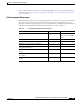
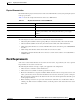
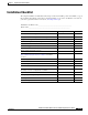
Table Of Contents
- Hardware Installation Guide for the Cisco 4451-X Integrated Services Router
- Contents
- Preface
- Overview of the Cisco 4451-X Integrated Services Router
- About the Cisco ISR 4451-X
- Safety Warnings
- Safety Warnings for Finland, Norway and Sweden
- Chassis Views
- Cisco ISR 4451-X Chassis
- Platform Summary
- Locating the Serial Number, PID, VID and CLEI
- Labels on Cisco ISR 4451-X
- For Additional Help Locating Labels on the Router
- Hardware Features
- Built-in Interface Ports
- Front Panel Ethernet Ports
- Dual Mode GE/SFP Ports
- USB Serial Console Port
- Front Panel PoE+ Ports
- Internal PoE card
- LED Indicators
- Removable and Interchangeable Modules and Cards
- Network Interface Modules
- Cisco UCS E-Series Server Modules
- Compact Flash
- Solid State Drives
- Packet Voice Digital Signal Processor Modules
- Memory
- Power Supplies
- Fans, Ventilation, and Airflow
- About Slots and Interfaces
- About Slot, Subslot (Bay), and Port Numbering
- Slot Numbering
- About Slot 0
- About Slot 1 and 2
- Additional Slots
- Subslot/Bay Numbering
- Gigabit Ethernet Management
- About Fixed Interfaces
- Specifications
- Periodic Inspection and Cleaning
- Preparing for Router Installation
- Standard Warning Statements
- General Safety Warnings
- Safety Recommendations
- Safety with Electricity
- Preventing Electrostatic Discharge Damage
- General Site Requirements
- General Precautions
- Site Selection Guidelines
- Site Environmental Requirements
- Physical Characteristics
- Rack Requirements
- Router Environmental Requirements
- Power Guidelines and Requirements
- Network Cabling Specifications
- Console and Auxiliary Port Considerations
- Console Port Connections
- Auxiliary Port Connections
- Preparing for Network Connections
- Ethernet Connections
- Required Tools and Equipment for Installation and Maintenance
- Installation Checklist
- Creating a Site Log
- Installing and Connecting the Router
- What You Need to Know
- Before You Begin
- Unpacking the Router
- Installing the Router
- Rack-Mounting the Chassis
- Attaching Rack-Mount Brackets
- Mounting the Router in a Rack
- Grounding the Chassis
- Setting the Chassis on a Desktop
- Chassis Grounding
- Connecting Power
- Connecting to AC Power
- Connecting to a Console Terminal or Modem
- Connecting to the Serial Port with Microsoft Windows
- Connecting to the Console Port with Mac OS X
- Connecting to the Console Port with Linux
- Installing the Cisco Microsoft Windows USB Device Driver
- Installing the Cisco Microsoft Windows XP USB Driver
- Installing the Cisco Microsoft Windows 2000 USB Driver
- Installing the Cisco Microsoft Windows Vista USB Driver
- Uninstalling the Cisco Microsoft Windows USB Driver
- Uninstalling the Cisco Microsoft Windows XP and 2000 USB Driver
- Uninstalling the Cisco Microsoft Windows Vista USB Driver
- Connecting to the Auxiliary Port
- Connecting WAN, LAN, and Voice Interfaces
- Ports and Cabling
- Connection Procedures and Precautions
- Initial Configuration
- Performing the Initial Configuration on the Router
- Using Cisco Setup Command Facility
- Completing the Configuration
- Using Cisco IOS-XE CLI-Manual Configuration
- Configuring the Router Hostname
- Configuring the Enable and Enable Secret Passwords
- Configuring the Console Idle Privileged EXEC Timeout
- Gigabit Ethernet Management Interface Overview
- Default Gigabit Ethernet Configuration
- Gigabit Ethernet Port Numbering
- Configuring Gigabit Ethernet Interfaces
- Configuration Examples
- Specifying a Default Route or Gateway of Last Resort
- Configuring IP Routing and IP Protocols
- Default Routes
- Default Network
- Gateway of Last Resort
- Configuration Examples
- Configuring Virtual Terminal Lines for Remote Console Access
- Configuration Examples
- Configuring the Auxiliary Line
- Verifying Network Connectivity
- Saving Your Router Configuration
- Saving Backup Copies of Configuration and System Image
- Configuration Examples
- Verifying the Initial Configuration
- ROM Monitor Overview and Basic Procedures
- ROM Monitor Overview
- Entering ROM Monitor Mode
- Checking the Current ROMmon Version
- Commonly Used ROM Monitor Commands
- Displaying the Available ROM Monitor Commands
- Examples
- Changing the ROM Monitor Prompt
- Displaying the Configuration Register Setting
- Environment Variable Settings
- Frequently Used Environmental Variables
- Displaying Environment Variable Settings
- Entering Environment Variable Settings
- Saving Environment Variable Settings
- Exiting ROM Monitor Mode
- Configuration Example
- Upgrading the ROMmon for a Router
- Example of Upgrade
- Installing and Upgrading Internal Modules and FRUs
- Safety Warnings
- Accessing Internal Modules
- Removing and Replacing the Chassis Cover
- Removing the Cover
- Replacing the Cover
- Locating Internal and External Slots for Modules
- Overview of the SSD Carrier Card NIM (NIM-SSD)
- Overview
- LEDs on the NIM-SSD
- Solid State Drives (SSD)
- Installing the SSD Drives into the NIM Carrier Card
- Removing the SSD Drives from the NIM-SSD
- Removing and Replacing the Cisco ISR 4451-X NIM-SSD Drives
- Removing the NIM-SSD from the Router
- Replacing the NIM-SSD on the Router
- Installing and Removing DDR DIMMs
- Locating and Orienting DIMM
- Removing a DIMM
- Installing a DIMM
- Installing and Removing NIMs and SMs
- Software Requirement for SMs
- Locating an SM or NIM
- Removing an SM or NIM
- Installing an SM
- Verifying SM Installation
- Installing and Removing the PVDM4
- Tools and Equipment Required During Installation
- PVDM4 Location and Orientation
- Installing the PVDM4 on the Motherboard of the Cisco ISR 4451-X
- Removing the PVDM4 from the Motherboard of the Cisco ISR 4451-X
- Installing the PVDM4 on the Cisco Fourth-Generation T1/E1 Voice and WAN NIM in the Cisco ISR 4451-X
- Removing the PVDM4 from the Cisco Fourth-Generation T1/E1 Voice and WAN Network Interface Module in the Cisco ISR 4451-X
- Removing and Replacing the USB Flash Token Memory Stick
- Replacing Power Supplies and Redundant Power Supplies
- Replacing the Cisco ISR 4451-X Power Supply
- Replacing the Power Supply on the Cisco ISR 4451-Xs
- Inserting PoE Supply in an Ethernet Switch Network Module
- Cisco ISR 4451-X Power and RPS Error Messages
- Replacing a Fan Tray
- Before Hot-Swapping a Fan Tray
- Replacing the Cisco ISR 4451-X Fan Tray
- Removing and Installing a CompactFlash Memory Card
- Preventing Electrostatic Discharge Damage
- Removing a CompactFlash Memory Card
- Installing a CompactFlash Memory Card
- Installing SFP Modules
- Laser Safety Guidelines
- Removing SFP Modules
- Removing, Replacing, and Installing an Internal PoE Card
- Online Insertion and Removal (OIR) and Hot-Swapping
2-16
Hardware Installation Guide for the Cisco 4451-X Integrated Services Router
OL-27644-01
Chapter 2 Preparing for Router Installation
Installation Checklist
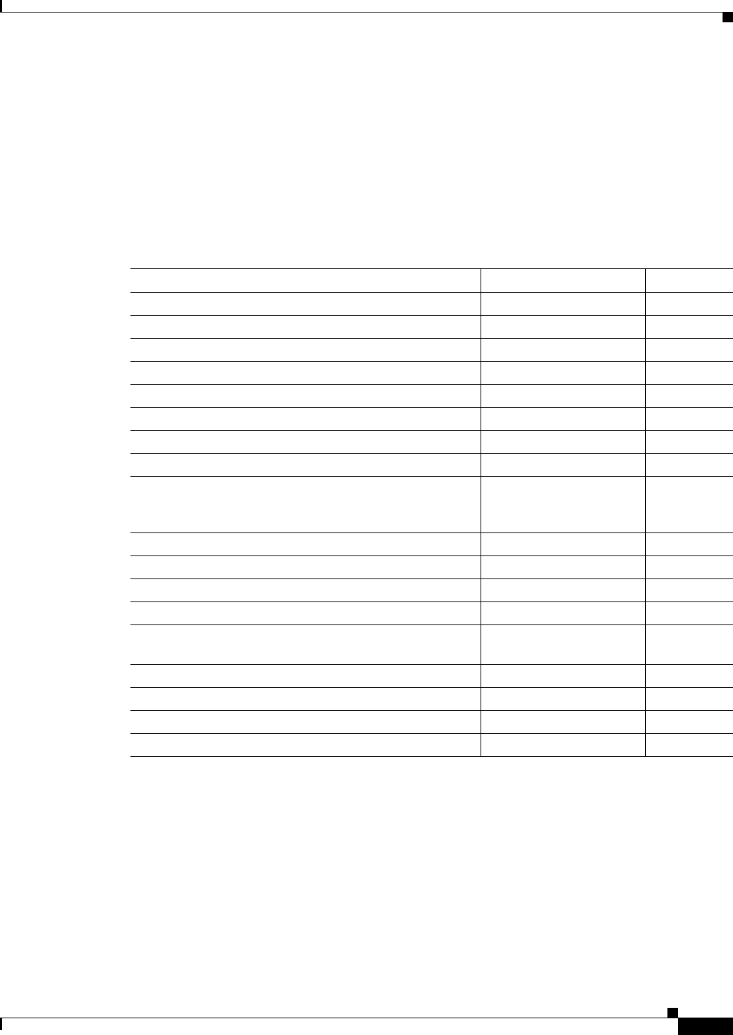
Installation Checklist
The sample installation checklist lists items and procedures for installing a new router. Make a copy of
this checklist and mark the entries when completed. Include a copy of the checklist for each router in
your site log (described in the next section, “Creating a Site Log”).
Installation checklist for site_____________________________________________
Router name_______________________________________________________
Task Verified by Date
Installation checklist copied
Background information placed in Site Log
Site power voltages verified
Installation site power check completed
Required tools available
Additional equipment available
Router received
Router quick start guide received
Regulatory Compliance and Safety Information for the
Cisco 4451-X Integrated Services Routers document
received
Product registration card received
Cisco.com contact information label received
Chassis components verified
Initial electrical connections established
ASCII terminal (for local configuration) or
modem (for remote configuration) available
Signal distance limits verified
Startup sequence steps completed
Initial operation verified
Software image verified