
- Cisco 4451-X Integrated Services Router Manual
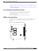
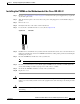
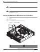
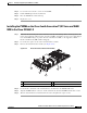
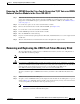
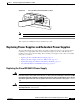
Table Of Contents
- Hardware Installation Guide for the Cisco 4451-X Integrated Services Router
- Contents
- Preface
- Overview of the Cisco 4451-X Integrated Services Router
- About the Cisco ISR 4451-X
- Safety Warnings
- Safety Warnings for Finland, Norway and Sweden
- Chassis Views
- Cisco ISR 4451-X Chassis
- Platform Summary
- Locating the Serial Number, PID, VID and CLEI
- Labels on Cisco ISR 4451-X
- For Additional Help Locating Labels on the Router
- Hardware Features
- Built-in Interface Ports
- Front Panel Ethernet Ports
- Dual Mode GE/SFP Ports
- USB Serial Console Port
- Front Panel PoE+ Ports
- Internal PoE card
- LED Indicators
- Removable and Interchangeable Modules and Cards
- Network Interface Modules
- Cisco UCS E-Series Server Modules
- Compact Flash
- Solid State Drives
- Packet Voice Digital Signal Processor Modules
- Memory
- Power Supplies
- Fans, Ventilation, and Airflow
- About Slots and Interfaces
- About Slot, Subslot (Bay), and Port Numbering
- Slot Numbering
- About Slot 0
- About Slot 1 and 2
- Additional Slots
- Subslot/Bay Numbering
- Gigabit Ethernet Management
- About Fixed Interfaces
- Specifications
- Periodic Inspection and Cleaning
- Preparing for Router Installation
- Standard Warning Statements
- General Safety Warnings
- Safety Recommendations
- Safety with Electricity
- Preventing Electrostatic Discharge Damage
- General Site Requirements
- General Precautions
- Site Selection Guidelines
- Site Environmental Requirements
- Physical Characteristics
- Rack Requirements
- Router Environmental Requirements
- Power Guidelines and Requirements
- Network Cabling Specifications
- Console and Auxiliary Port Considerations
- Console Port Connections
- Auxiliary Port Connections
- Preparing for Network Connections
- Ethernet Connections
- Required Tools and Equipment for Installation and Maintenance
- Installation Checklist
- Creating a Site Log
- Installing and Connecting the Router
- What You Need to Know
- Before You Begin
- Unpacking the Router
- Installing the Router
- Rack-Mounting the Chassis
- Attaching Rack-Mount Brackets
- Mounting the Router in a Rack
- Grounding the Chassis
- Setting the Chassis on a Desktop
- Chassis Grounding
- Connecting Power
- Connecting to AC Power
- Connecting to a Console Terminal or Modem
- Connecting to the Serial Port with Microsoft Windows
- Connecting to the Console Port with Mac OS X
- Connecting to the Console Port with Linux
- Installing the Cisco Microsoft Windows USB Device Driver
- Installing the Cisco Microsoft Windows XP USB Driver
- Installing the Cisco Microsoft Windows 2000 USB Driver
- Installing the Cisco Microsoft Windows Vista USB Driver
- Uninstalling the Cisco Microsoft Windows USB Driver
- Uninstalling the Cisco Microsoft Windows XP and 2000 USB Driver
- Uninstalling the Cisco Microsoft Windows Vista USB Driver
- Connecting to the Auxiliary Port
- Connecting WAN, LAN, and Voice Interfaces
- Ports and Cabling
- Connection Procedures and Precautions
- Initial Configuration
- Performing the Initial Configuration on the Router
- Using Cisco Setup Command Facility
- Completing the Configuration
- Using Cisco IOS-XE CLI-Manual Configuration
- Configuring the Router Hostname
- Configuring the Enable and Enable Secret Passwords
- Configuring the Console Idle Privileged EXEC Timeout
- Gigabit Ethernet Management Interface Overview
- Default Gigabit Ethernet Configuration
- Gigabit Ethernet Port Numbering
- Configuring Gigabit Ethernet Interfaces
- Configuration Examples
- Specifying a Default Route or Gateway of Last Resort
- Configuring IP Routing and IP Protocols
- Default Routes
- Default Network
- Gateway of Last Resort
- Configuration Examples
- Configuring Virtual Terminal Lines for Remote Console Access
- Configuration Examples
- Configuring the Auxiliary Line
- Verifying Network Connectivity
- Saving Your Router Configuration
- Saving Backup Copies of Configuration and System Image
- Configuration Examples
- Verifying the Initial Configuration
- ROM Monitor Overview and Basic Procedures
- ROM Monitor Overview
- Entering ROM Monitor Mode
- Checking the Current ROMmon Version
- Commonly Used ROM Monitor Commands
- Displaying the Available ROM Monitor Commands
- Examples
- Changing the ROM Monitor Prompt
- Displaying the Configuration Register Setting
- Environment Variable Settings
- Frequently Used Environmental Variables
- Displaying Environment Variable Settings
- Entering Environment Variable Settings
- Saving Environment Variable Settings
- Exiting ROM Monitor Mode
- Configuration Example
- Upgrading the ROMmon for a Router
- Example of Upgrade
- Installing and Upgrading Internal Modules and FRUs
- Safety Warnings
- Accessing Internal Modules
- Removing and Replacing the Chassis Cover
- Removing the Cover
- Replacing the Cover
- Locating Internal and External Slots for Modules
- Overview of the SSD Carrier Card NIM (NIM-SSD)
- Overview
- LEDs on the NIM-SSD
- Solid State Drives (SSD)
- Installing the SSD Drives into the NIM Carrier Card
- Removing the SSD Drives from the NIM-SSD
- Removing and Replacing the Cisco ISR 4451-X NIM-SSD Drives
- Removing the NIM-SSD from the Router
- Replacing the NIM-SSD on the Router
- Installing and Removing DDR DIMMs
- Locating and Orienting DIMM
- Removing a DIMM
- Installing a DIMM
- Installing and Removing NIMs and SMs
- Software Requirement for SMs
- Locating an SM or NIM
- Removing an SM or NIM
- Installing an SM
- Verifying SM Installation
- Installing and Removing the PVDM4
- Tools and Equipment Required During Installation
- PVDM4 Location and Orientation
- Installing the PVDM4 on the Motherboard of the Cisco ISR 4451-X
- Removing the PVDM4 from the Motherboard of the Cisco ISR 4451-X
- Installing the PVDM4 on the Cisco Fourth-Generation T1/E1 Voice and WAN NIM in the Cisco ISR 4451-X
- Removing the PVDM4 from the Cisco Fourth-Generation T1/E1 Voice and WAN Network Interface Module in the Cisco ISR 4451-X
- Removing and Replacing the USB Flash Token Memory Stick
- Replacing Power Supplies and Redundant Power Supplies
- Replacing the Cisco ISR 4451-X Power Supply
- Replacing the Power Supply on the Cisco ISR 4451-Xs
- Inserting PoE Supply in an Ethernet Switch Network Module
- Cisco ISR 4451-X Power and RPS Error Messages
- Replacing a Fan Tray
- Before Hot-Swapping a Fan Tray
- Replacing the Cisco ISR 4451-X Fan Tray
- Removing and Installing a CompactFlash Memory Card
- Preventing Electrostatic Discharge Damage
- Removing a CompactFlash Memory Card
- Installing a CompactFlash Memory Card
- Installing SFP Modules
- Laser Safety Guidelines
- Removing SFP Modules
- Removing, Replacing, and Installing an Internal PoE Card
- Online Insertion and Removal (OIR) and Hot-Swapping

6-34
Hardware Installation Guide for the Cisco 4451-X Integrated Services Router
OL-27644-01
Chapter 6 Installing and Upgrading Internal Modules and FRUs
Replacing a Fan Tray
Warning
Care should be taken while removing the power supplies and power inverters (especially in boost
mode of operation). If the total power consumption is higher than can be supported by one power
supply alone and in this condition a power supply is removed, the hardware can be damaged. This
may then result in the system being unstable or unusable.
The following messages are expected behavior when you try to reload or insert a PoE supply in a router
with Ethernet Switch Network Module:
Aug 10 18:29:40.331: %ILPM_FAULT-5-ILPM_NOTICE: Notice: Inline power supply is being
started.
*Aug 10 18:29:40.331: %ILPM_FAULT-5-ILPM_WARNING: Warning: Ethernet Switch Network Modules
with PoE Support need to be reloaded to function properly.
*Aug 10 18:29:40.691: %SYS-5-RESTART: System restarted -- Cisco IOS Software, C2900
Software (C2900-UNIVERSALK9-M), Version 15.0(1)M2, RELEASE SOFTWARE (fc2)
This warning message is not an indication of any error in the system but a warning upon system reload
or PoE power supply restoration.
Upon PoE power supply insertion, inline power supply restores automatically in the router. After the
insertion, resets are needed for the switch modules in the router for the PoE supply to work properly.
If there are two PoE supplies, the power supplies can operate in a boost mode or redundant mode. In a
boost mode, the total power supplied is a sum of the two power supplies capacity. In a redundant mode,
if one of the PoE supply fails, the other PoE will supply power.
Cisco ISR 4451-X Power and RPS Error Messages
There are several RPS error messages unique to the Cisco ISR 4451-Xs. The messages appear on the
router console terminal.
Replacing a Fan Tray
The Cisco ISR 4451-Xs have hot-swappable fan trays that are field replaceable units (FRUs). The fan
tray includes all of the router fans in one assembly. If a fan fails, replace the tray using a flat-blade or
Phillips screwdriver.
Before Hot-Swapping a Fan Tray
Before hot-swapping a fan tray, read the safety precautions below.
• Read the entire procedure and have the required tools available.
• Do not attempt the hot-swap in ambient air temperature above 90°F (32°C).
• Do not attempt the hot-swap at an altitude above 6000 feet (1829 meters).
• When the router is being operated, it is recommended to change the fans in the Cisco ISR 4451-X
within 2 minutes to ensure the router does not overheat:
Replacing the Cisco ISR 4451-X Fan Tray
To replace the fan tray, complete the following steps: