Hardware Installation Guide for the Cisco 4451-X Integrated Services Router November 21, 2013 Cisco Systems, Inc. www.cisco.com Cisco has more than 200 offices worldwide. Addresses, phone numbers, and fax numbers are listed on the Cisco website at www.cisco.com/go/offices.
THE SPECIFICATIONS AND INFORMATION REGARDING THE PRODUCTS IN THIS MANUAL ARE SUBJECT TO CHANGE WITHOUT NOTICE. ALL STATEMENTS, INFORMATION, AND RECOMMENDATIONS IN THIS MANUAL ARE BELIEVED TO BE ACCURATE BUT ARE PRESENTED WITHOUT WARRANTY OF ANY KIND, EXPRESS OR IMPLIED. USERS MUST TAKE FULL RESPONSIBILITY FOR THEIR APPLICATION OF ANY PRODUCTS.
C O N T E N T S Preface CHAPTER 1 ix Overview of the Cisco 4451-X Integrated Services Router About the Cisco ISR 4451-X 1-1 Safety Warnings 1-2 Safety Warnings for Finland, Norway and Sweden Chassis Views 1-3 Cisco ISR 4451-X Chassis Platform Summary 1-7 1-1 1-3 1-4 Locating the Serial Number, PID, VID and CLEI 1-7 Labels on Cisco ISR 4451-X 1-8 For Additional Help Locating Labels on the Router 1-8 Hardware Features 1-9 Built-in Interface Ports 1-9 Front Panel Ethernet Ports 1-10 Dual Mode GE/SF
Contents Additional Slots 1-20 Subslot/Bay Numbering 1-20 Gigabit Ethernet Management 1-20 About Fixed Interfaces 1-20 Specifications 1-20 Periodic Inspection and Cleaning CHAPTER 2 Preparing for Router Installation 1-25 2-1 Standard Warning Statements 2-1 General Safety Warnings 2-1 Safety Recommendations 2-5 Safety with Electricity 2-5 Preventing Electrostatic Discharge Damage General Site Requirements 2-7 General Precautions 2-7 Site Selection Guidelines 2-7 Site Environmental Requirements Physi
Contents Mounting the Router in a Rack 3-7 Grounding the Chassis 3-9 Setting the Chassis on a Desktop 3-10 Chassis Grounding 3-11 Connecting Power 3-12 Connecting to AC Power 3-13 Connecting to a Console Terminal or Modem 3-14 Connecting to the Serial Port with Microsoft Windows Connecting to the Console Port with Mac OS X 3-15 Connecting to the Console Port with Linux 3-16 3-14 Installing the Cisco Microsoft Windows USB Device Driver 3-16 Installing the Cisco Microsoft Windows XP USB Driver 3-17 Ins
Contents Gateway of Last Resort 4-13 Configuration Examples 4-15 Configuring Virtual Terminal Lines for Remote Console Access Configuration Examples 4-17 Configuring the Auxiliary Line 4-17 Verifying Network Connectivity 4-19 Saving Your Router Configuration 4-20 Saving Backup Copies of Configuration and System Image Configuration Examples 4-21 Verifying the Initial Configuration CHAPTER 5 4-20 4-23 ROM Monitor Overview and Basic Procedures ROM Monitor Overview 4-16 5-1 5-1 Entering ROM Monitor Mo
Contents Overview 6-7 LEDs on the NIM-SSD 6-8 Solid State Drives (SSD) 6-10 Installing the SSD Drives into the NIM Carrier Card 6-12 Removing the SSD Drives from the NIM-SSD 6-13 Removing and Replacing the Cisco ISR 4451-X NIM-SSD Drives Removing the NIM-SSD from the Router 6-16 Replacing the NIM-SSD on the Router 6-18 6-15 Installing and Removing DDR DIMMs 6-18 Locating and Orienting DIMM 6-18 Removing a DIMM 6-20 Installing a DIMM 6-21 Installing and Removing NIMs and SMs 6-23 Software Requirement for
Contents Installing a CompactFlash Memory Card 6-37 Installing SFP Modules 6-38 Laser Safety Guidelines 6-40 Removing SFP Modules 6-40 Removing, Replacing, and Installing an Internal PoE Card CHAPTER 7 Online Insertion and Removal (OIR) and Hot-Swapping OIR Procedures 7-2 Removing a Module 7-2 Inserting a Data or Voice Module Hot-Swapping Procedures 6-41 7-1 7-2 7-2 Hardware Installation Guide for the Cisco 4451-X Integrated Services Router viii
Preface This preface describes the objectives, audience, organization and conventions of this guide, and the references that accompany this document set.
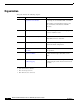
Organization This guide includes the following chapters: Chapter Title Description 1 Overview of the Cisco 4451-X Integrated Services Router Describes the router chassis views, information for locating the serial number, PID1, and UDI2. Also includes general hardware features, slot, port, and interface information; and LED indicators. 2 Preparing for Router Installation Describes site requirements and the equipment needed to install the router.
Conventions This document uses the following conventions: Convention Indication bold font Commands and keywords and user-entered text appear in bold font. italic font Document titles, new or emphasized terms, and arguments for which you supply values are in italic font. [ ] Elements in square brackets are optional. {x | y | z } Required alternative keywords are grouped in braces and separated by vertical bars.
Warning IMPORTANT SAFETY INSTRUCTIONS This warning symbol means danger. You are in a situation that could cause bodily injury. Before you work on any equipment, be aware of the hazards involved with electrical circuitry and be familiar with standard practices for preventing accidents. Use the statement number provided at the end of each warning to locate its translation in the translated safety warnings that accompanied this device.
Avvertenza IMPORTANTI ISTRUZIONI SULLA SICUREZZA Questo simbolo di avvertenza indica un pericolo. La situazione potrebbe causare infortuni alle persone. Prima di intervenire su qualsiasi apparecchiatura, occorre essere al corrente dei pericoli relativi ai circuiti elettrici e conoscere le procedure standard per la prevenzione di incidenti. Utilizzare il numero di istruzione presente alla fine di ciascuna avvertenza per individuare le traduzioni delle avvertenze riportate in questo documento.
Hardware Installation Guide for the Cisco 4451-X Integrated Services Router xiv OL-27644-01
Aviso INSTRUÇÕES IMPORTANTES DE SEGURANÇA Este símbolo de aviso significa perigo. Você se encontra em uma situação em que há risco de lesões corporais. Antes de trabalhar com qualquer equipamento, esteja ciente dos riscos que envolvem os circuitos elétricos e familiarize-se com as práticas padrão de prevenção de acidentes. Use o número da declaração fornecido ao final de cada aviso para localizar sua tradução nos avisos de segurança traduzidos que acompanham o dispositivo.
Hardware Installation Guide for the Cisco 4451-X Integrated Services Router xvi OL-27644-01
Warning When installing the product, please use the provided or designated connection cables/power cables/AC adaptors. Using any other cables/adaptors could cause a malfunction or a fire. Electrical Appliance and Material Safety Law prohibits the use of UL-certified cables (that have the “UL” shown on the code) for any other electrical devices than products designated by CISCO.
Searching for Cisco Documents To search an HTML document using a web browser, press Ctrl-F (Windows) or Cmd-F (Apple). In most browsers, the option to search whole words only, invoke case sensitivity, or search forward and backward is also available. To search a PDF document in Adobe Reader, use the basic Find toolbar (Ctrl-F) or the Full Reader Search window (Shift-Ctrl-F). Use the Find toolbar to find words or phrases within a specific document.
CH A P T E R 1 Overview of the Cisco 4451-X Integrated Services Router About the Cisco ISR 4451-X The Cisco 4451-X Integrated Services Router (ISR) is a modular router with LAN and WAN connectivity and supports several interface modules, including Cisco Service Modules (SMs), or Enhanced Service Modules (SM-X), and Network Interface Modules (NIMs). The router has slots that support the interface modules and modular Solid State Drives (SSDs).
Chapter 1 Overview of the Cisco 4451-X Integrated Services Router Safety Warnings • 1 RJ45 Console • 1 RJ45 AUX port with full modem control signals • 4 10/100/1000 RJ-45 Ethernet ports (labeled GE 0/0/0, 0/0/1, 0/0/2, and 0/0/3) • 4 100/1000 SFP Ethernet ports (labeled SFP 0/0/0, 0/0/1, 0/0/2, and 0/0/3) • LEDs for Ethernet and console status • LEDs for SATA hard disk drive activity and status (available on certain models) • Two DDR3 240 pin Control Plane DIMM slots which can be replaced •
Chapter 1 Overview of the Cisco 4451-X Integrated Services Router Chassis Views Warning Ultimate disposal of this product should be handled according to all national laws and regulations. Statement 1040 Warning Only trained and qualified personnel should be allowed to install, replace, or service this equipment. Statement 1030 Safety Warnings for Finland, Norway and Sweden Warning statement 1017 applies to the countries of Finland, Norway, and Sweden.
Chapter 1 Overview of the Cisco 4451-X Integrated Services Router Chassis Views Cisco ISR 4451-X Chassis Figure 1-1 on page 1-4— Bezel view with one PSU Figure 1-2 on page 1-5— Bezel view with two PSUs Figure 1-3 on page 1-5— Back panel slots and ports Figure 1-4 on page 1-6—Bezel side LEDs Figure 1-1 Bezel View of the Cisco ISR 4451-X with one Power Supply Unit 1 2 3 Cisco 4400 Series PSU1 PSU2 INT POE1 POE2 BOOST FLASH TEMP PWR VM FAN STAT 285694 POE 5 4 1 Router fan tray 2 LEDs
Chapter 1 Overview of the Cisco 4451-X Integrated Services Router Chassis Views Figure 1-2 Bezel side of the Cisco ISR 4451-X with two PSUs 1 2 3 Cisco 4400 Series PSU1 PSU2 INT POE1 POE2 BOOST FLASH TEMP PWR VM FAN STAT 285695 POE 5 4 1 Router fan tray 2 LEDs 3 Router power On/Off switch 4 AC power supply unit (P1) 5 AC power supply unit (P0) Back Panel (I/O Side) Slots and Connectors on the Cisco ISR 4451-X 1 2 3 5 6 4 8 9 10 11 7 1 2 23 22 21 20 18 19 285
Chapter 1 Overview of the Cisco 4451-X Integrated Services Router Chassis Views 17 SFP Gigabit Ethernet GE 0/0/1 18 LEDs for the GE 0/0/1 interface 19 RJ45 Gigabit Ethernet port GE 0/0/1 20 Serial Console Port 21 Console port USB 0 and USB 1 Figure 1-4 Bezel Side LEDS of the Single PSU Cisco ISR 4451-X Model 1 2 3 PSU0 PSU1 INT 4 5 FLASH TEMP 6 PWR POE POE0 POE1 BOOST VM FAN STAT 12 11 10 9 8 7 Cisco 4400 Series PSU1 PSU0 PSU2 PSU1 POE1 POE0 POE2 BOOST POE1 BOOST INT INT
Chapter 1 Overview of the Cisco 4451-X Integrated Services Router Locating the Serial Number, PID, VID and CLEI Platform Summary Figure 1-5 shows an internal view of the Cisco ISR 4451-X with all the parts and module location. Figure 1-5 Platform Summary of the Cisco ISR 4451-X 2 3 285699 1 9 8 6 5 7 4 1. ISC slot 2. CPU 3. DIMM 4. Modular HDD Slot (Factory-configured) 5. Modular HDD slot (Factory-configured) 6. NIM 2 (single-wide) 7. NIM slot divider 8.
Chapter 1 Overview of the Cisco 4451-X Integrated Services Router Locating the Serial Number, PID, VID and CLEI mode in Cisco Internet Operating System (IOS) software. For additional information on the UDI or how to obtain a PAK, see the Cisco Software Activation on Integrated Services Routers document on Cisco.com. The UDI has two main components: • Product ID (PID) • Serial number (SN) Labels on Cisco ISR 4451-X Figure 1-6 shows the location of the labels on the Cisco ISR 4451-Xs.
Chapter 1 Overview of the Cisco 4451-X Integrated Services Router Hardware Features The Cisco Product Identification tool can be accessed at the following URL: http://tools.cisco.com/Support/CPI/index.do Hardware Features This section describes the hardware features in the Cisco ISR 4451-X.
Chapter 1 Overview of the Cisco 4451-X Integrated Services Router Hardware Features Front Panel Ethernet Ports There are 4 front panel Ethernet ports. Each port independently supports dual-media types, RJ45 copper or SFPs. Dual Mode GE/SFP Ports There are Dual Mode ports available on the Cisco ISR 4451-X that can function as GE or SFP ports. GE Ports The GE RJ-45 copper interface ports support 10BASE-T, 100BASE-TX, and 1000BASE-T.
Chapter 1 Overview of the Cisco 4451-X Integrated Services Router Hardware Features Internal PoE card The internal PoE daughter card provides a total of 30.8 Watts of power across the 2 ports. LED Indicators Table 1-1 summarizes the LED indicators that are located in the router bezel or chassis, but not on the interface cards and modules. Note For module LEDs, please refer to the respective module installation guides for each module.
Chapter 1 Overview of the Cisco 4451-X Integrated Services Router Hardware Features Table 1-1 LED Indicators on the Cisco ISR 4451-X (continued) LED Represents L Green Ethernet ports 2 and 3 and Off Management Ethernet Link (right) S (right) SFP EN SFP S SER CON (right) USB CON Color Green Ethernet ports 2, and 3 and Management Ethernet Speed Off Port 0, 1, 2, Green and 3 Enable Amber Description Location Ethernet cable present and link established with other side. I/O side No link.
Chapter 1 Overview of the Cisco 4451-X Integrated Services Router Hardware Features Table 1-1 LED LED Indicators on the Cisco ISR 4451-X (continued) Represents Color Description Location POE PSU Power Over Ethernet (not supported Power in Cisco Supply Unit 1 and 2 IOS XE Status 3.8) Green PSU is on and providing power. Bezel side Amber PSU is on but with errors or in a failure condition. Off PSU is off.
Chapter 1 Overview of the Cisco 4451-X Integrated Services Router Hardware Features Internal Slots • Packet Voice Digital Signal Processor Modules, page 1-16 • Memory, page 1-16 • Compact Flash, page 1-15 Because of physical differences with the new slots, legacy network modules and legacy Service Modules require an adapter for installation. Warning Only trained and qualified personnel should be allowed to install, replace, or service this equipment.
Chapter 1 Overview of the Cisco 4451-X Integrated Services Router Hardware Features Table 1-2 shows the number of internal and external slots on Cisco ISR 4451-Xs. It also shows the number of EHWICs and SMs that are supported in the router slots at any time. Note Table 1-2 is valid for Cisco IOS XE release 3.9.
Chapter 1 Overview of the Cisco 4451-X Integrated Services Router Hardware Features Packet Voice Digital Signal Processor Modules The Packet Voice Digital Signal Processor Modules (PVDM4s) add additional voice capabilities to the Cisco ISR 4451-Xs. The PVDM4 is installed inside the chassis of the router. See the “Installing the PVDM4 on the Motherboard of the Cisco ISR 4451-X” section on page 6-27 for installation instructions.
Chapter 1 Overview of the Cisco 4451-X Integrated Services Router About Slots and Interfaces Fans, Ventilation, and Airflow Chassis Ventilation An internal fan tray consisting of 4 fans provides chassis cooling. An onboard temperature sensor controls the fan speed. The fans are always on when the router is powered on. Under most conditions, the fans operate at the slowest speed to conserve power and reduce fan noise.
Chapter 1 Overview of the Cisco 4451-X Integrated Services Router About Slots and Interfaces • In most cases, the router designates its interfaces using a 3-tuple notation that lists the slot, bay, and port. The 3-tuple value is zero based. An example of a 3-tuple is 0/1/2. This refers to slot 0, the second bay in slot 0 (the first bay is 0 so the second bay is 1), and the third port in bay 1. See Table 1-4 for more examples.
Chapter 1 Overview of the Cisco 4451-X Integrated Services Router About Slots and Interfaces Figure 1-9 Ports and Slots on the Cisco ISR 4451-Xs 1 3 4 5 6 7 8 2 L 16 15 14 13 12 11 10 9 1 Gigabit Ethernet management port 2 USB port 0 3 USB console 4 Auxiliary port 5 Gigabit Ethernet port 0 6 Small-form-factor pluggable (SFP) 0 7 SFP 2 8 Gigabit Ethernet port 2 9 Gigabit Ethernet port 3 10 SFP 3 11 SFP 1 12 Console port 13 Gigabit Ethernet port 1 14 HDD 2 LED 15 HDD
Chapter 1 Overview of the Cisco 4451-X Integrated Services Router Specifications About Slot 1 and 2 Slot 1 and slot 2 are NIM slots. All enhanced SM slots start with 1. Additional Slots The Cisco ISR 4451-Xs have the following additional slots: • P0: Field upgradable power supply slot 0 • P1: Field upgradable/replaceable power supply slot 1. • INT-POE: Internal PoE card slot.
Chapter 1 Overview of the Cisco 4451-X Integrated Services Router Specifications Table 1-5 Cisco ISR 4451-X Router Specifications (continued) Description Specification Weight with AC PS (w/o modules) 28.5 lbs (12.92 kg) Weight with dual AC-PoE PS (w/o modules) 30.0 lbs (13.6 kg) Weight with dual AC + PoE adaptor (w/o modules) 38.0-40.0 lbs (17.23-18.14 kg) Power AC input power • Input voltage 100 to 240 VAC, autoranging • Frequency 47 to 63 Hz • Input current 5.
Chapter 1 Overview of the Cisco 4451-X Integrated Services Router Specifications Table 1-5 Cisco ISR 4451-X Router Specifications (continued) Description Specification Weight with AC PS (w/o modules) 28.5 lbs (12.92 kg) Weight with dual AC-PoE PS (w/o modules) 30.0 lbs (13.6 kg) Weight with dual AC + PoE adaptor (w/o modules) 38.0-40.0 lbs (17.23-18.14 kg) Power AC input power • Input voltage 100 to 240 VAC, autoranging • Frequency 47 to 63 Hz • Input current 5.
Chapter 1 Overview of the Cisco 4451-X Integrated Services Router Specifications Table 1-5 Cisco ISR 4451-X Router Specifications (continued) Description Specification Acoustic: Sound Pressure (Typical/Maximum) 54.4 to 67.4 dBA Acoustic: Sound Power (Typical/Maximum) 62.6 to 74.
Chapter 1 Overview of the Cisco 4451-X Integrated Services Router Specifications Table 1-5 Cisco ISR 4451-X Router Specifications (continued) Description Specification Immunity compliance CISPR24 ITE-Immunity characteristics, Limits and methods of measurement EN 55024 ITE-Immunity characteristics, Limits and methods of measurement EN 50082-1 Electromagnetic compatibility - Generic immunity standard - Part 1 EN 300-386 Electromagnetic compatibility for TNE SD/EMI EN 61000-6-1 For detailed compliance i
Chapter 1 Overview of the Cisco 4451-X Integrated Services Router Periodic Inspection and Cleaning Periodic Inspection and Cleaning Periodic inspection and cleaning of the external surface of the router is recommended to minimize the negative impact of environmental dust or debris. The frequency of inspection and cleaning is dependent upon the severity of the environmental conditions, but a minimum of every six months is recommended. Cleaning involves vacuuming of router air intake and exhaust vents.
CH A P T E R 2 Preparing for Router Installation This document provides preinstallation information, such as recommendations and requirements that should be before installing your router.
Chapter 2 Preparing for Router Installation Standard Warning Statements Warning Ultimate disposal of this product should be handled according to all national laws and regulations. Statement 1040 Warning Installation of the equipment must comply with local and national electrical codes. Statement 1074 Warning To comply with the Class A emissions requirements shielded twisted pair T1/E1 cables must be used for SPA-8-Port Channelized T1/E1 SPA (SPA-8XCHT1/E1) on the Cisco ISR 4451-Xs.
Chapter 2 Preparing for Router Installation Standard Warning Statements Warning The plug-socket combination must be accessible at all times, because it serves as the main disconnecting device. Statement 1019 Warning Hazardous voltage or energy may be present on the DC power terminals. Always replace cover when terminals are not in service. Be sure uninsulated conductors are not accessible when cover is in place. Statement 1075 Warning Use copper conductors only.
Chapter 2 Preparing for Router Installation Standard Warning Statements Warning Do not touch or bridge the metal contacts on the battery. Unintentional discharge of the batteries can cause serious burns. Statement 341 Warning To prevent personal injury or damage to the chassis, never attempt to lift or tilt the chassis using the handles on modules (such as power supplies, fans, or cards); these types of handles are not designed to support the weight of the unit.
Chapter 2 Preparing for Router Installation Safety Recommendations Warning Do not use this product near water; for example, near a bath tub, wash bowl, kitchen sink or laundry tub, in a wet basement, or near a swimming pool. Statement 1035 Warning Never install telephone jacks in wet locations unless the jack is specifically designed for wet locations. Statement 1036 Warning No user-serviceable parts inside. Do not open.
Chapter 2 Preparing for Router Installation Safety Recommendations Warning Do not work on the system or connect or disconnect cables during periods of lightning activity. Statement 1001 Warning Read the installation instructions before connecting the system to the power source. Statement 1004 Warning The covers are an integral part of the safety design of the product. Do not operate the unit without the covers installed.
Chapter 2 Preparing for Router Installation General Site Requirements Preventing Electrostatic Discharge Damage Electrostatic discharge (ESD) can damage equipment and impair electrical circuitry. It can occur if electronic printed circuit cards are improperly handled and can cause complete or intermittent failures. Always follow ESD prevention procedures when removing and replacing modules: Caution • Ensure that the router chassis is electrically connected to ground.
Chapter 2 Preparing for Router Installation General Site Requirements The Cisco ISR 4451-Xs are designed to meet the industry EMC, safety, and environmental standards described in the Regulatory, Safety, and Compliance Information for Cisco 4451-X Integrated Services Routers document. Site Environmental Requirements Environmental monitoring in the Cisco ISR 4451-X protects the system and components from damage caused by excessive voltage and temperature conditions.
Chapter 2 Preparing for Router Installation Rack Requirements Physical Characteristics Be familiar with the physical characteristics of the Cisco ISR 4451-X to assist you in placing the system in the proper location. Table 2-2 shows the weight and dimensions of the Cisco ISR 4451-X. Table 2-2 Physical Characteristics of Cisco ISR 4451-Xs Characteristics Cisco ISR 4451-Xs Height 3.5 in. (8.89 cm.)—2RU rack-mount Width 17.25 in. (43.815 cm.)—19-inch rack-mount Depth 18.7 in. (47.498 cm.
Chapter 2 Preparing for Router Installation Router Environmental Requirements Router Environmental Requirements Cisco ISR 4451-Xs can be placed on a desktop or installed in a rack. The location of your router and the layout of your equipment rack or wiring room are extremely important considerations for proper operation. Equipment placed too close together, inadequate ventilation, and inaccessible panels can cause malfunctions and shutdowns, and can make maintenance difficult.
Chapter 2 Preparing for Router Installation Power Guidelines and Requirements Power Guidelines and Requirements Check the power at your site to ensure that you are receiving “clean” power (free of spikes and noise). Install a power conditioner if necessary. The AC power supply includes the following features: • Autoselects either 110 V or 220 V operation. • All units include a 6-foot (1.8-meter) electrical power cord.
Chapter 2 Preparing for Router Installation Network Cabling Specifications Console and Auxiliary Port Considerations The router includes an asynchronous serial console port and an auxiliary port. The console and auxiliary ports provide access to the router either locally using a console terminal connected to the console port, or remotely using a modem connected to the auxiliary port.
Chapter 2 Preparing for Router Installation Network Cabling Specifications The Cisco Windows USB Console Driver allows plugging and unplugging the USB cable from the console port without affecting Windows HyperTerminal operations. No special drivers are needed for Mac OS X or Linux. Only one console port can be active at a time. When a cable is plugged into the USB console port, the RJ-45 port becomes inactive. Conversely, when the USB cable is removed from the USB port, the RJ-45 port becomes active.
Chapter 2 Preparing for Router Installation Required Tools and Equipment for Installation and Maintenance Preparing for Network Connections When setting up your router, consider distance limitations and potential electromagnetic interference (EMI) as defined by the applicable local and international regulations.
Chapter 2 Preparing for Router Installation Required Tools and Equipment for Installation and Maintenance You need the following tools and equipment to install and upgrade the router and its components: • ESD-preventive cord and wrist strap • Number 2 Phillips screwdriver • Phillips screwdrivers: small, 3/16-in. (4 to 5 mm) and medium, 1/4-in.
Chapter 2 Preparing for Router Installation Installation Checklist Installation Checklist The sample installation checklist lists items and procedures for installing a new router. Make a copy of this checklist and mark the entries when completed. Include a copy of the checklist for each router in your site log (described in the next section, “Creating a Site Log”).
Chapter 2 Preparing for Router Installation Creating a Site Log Creating a Site Log The Site Log provides a record of all actions related to the router. Keep it in an accessible place near the chassis where anyone who performs tasks has access to it. Use the installation checklist to verify steps in the installation and maintenance of the router. Site Log entries might include the following information: • Installation progress—Make a copy of the installation checklist and insert it into the site log.
CH A P T E R 3 Installing and Connecting the Router This document describes how to install and connect the Cisco 4451-X Integrated Services Routers (ISRs) to LAN, WAN, and Voice networks. The following sections provide technical details.
Chapter 3 Installing and Connecting the Router Warning This equipment must be grounded. Never defeat the ground conductor or operate the equipment in the absence of a suitably installed ground conductor. Contact the appropriate electrical inspection authority or an electrician if you are uncertain that suitable grounding is available. Statement 1024 Warning Before opening the unit, disconnect the telephone-network cables to avoid contact with telephone-network voltages.
Chapter 3 Installing and Connecting the Router What You Need to Know What You Need to Know CLI Console Access Use the USB console port on the router to access the Cisco Internet Operating System (IOS-XE) command line interface (CLI) on the router and perform configuration tasks. A terminal emulation program is required to establish communication between the router and a PC. See the “Connecting to a Console Terminal or Modem” section on page 3-14 for instructions.
Chapter 3 Installing and Connecting the Router Unpacking the Router In addition, depending on the type of modules you plan to use, you might need the following equipment to connect a port to an external network: • Cables for connection to the WAN and LAN ports (dependent on configuration) Note For more information on cable specifications, see the Cisco Modular Access Router Cable Specifications document on Cisco.com.
Chapter 3 Installing and Connecting the Router Installing the Router Rack-Mounting the Chassis Warning If the rack is provided with stabilizing devices, install the stabilizers before mounting or servicing the unit in the rack. Statement 1006 Warning This equipment must be grounded. Never defeat the ground conductor or operate the equipment in the absence of a suitably installed ground conductor.
Chapter 3 Installing and Connecting the Router Installing the Router Bracket Installation for Front Mounting 2 302953 Figure 3-1 1 2 1 1 23-inch SBC1 brackets 2 19-inch EIA brackets 1.
Chapter 3 Installing and Connecting the Router Installing the Router Bracket Installation for Back Mounting 302955 Figure 3-3 1 2 2 1 1 23-inch SBC brackets Figure 3-4 19-inch EIA brackets Bracket Installation for Center-Back Mounting 2 302956 1 2 2 1 1 23-inch SBC brackets 2 19-inch EIA brackets Mounting the Router in a Rack After you attach the rack-mount brackets to the router chassis, use the screws provided with the rack to install the chassis in the rack. (See Figure 3-5.
Chapter 3 Installing and Connecting the Router Installing the Router Tip For both the 19-inch EIA brackets and the 23-inch SBC brackets, start the lower pair of screws first, and rest the brackets on the lower screws while you insert the upper pair of screws. Tip The screw slots in the brackets are spaced to line up with every second pair of screw holes in the rack. When the correct screw holes are used, the small threaded holes in the brackets line up with unused screw holes in the rack.
Chapter 3 Installing and Connecting the Router Installing the Router Figure 3-5 Mounting the Chassis in a Rack (Typical) 302994 SP 1 1 Mounting screws (4) Figure 3-6 shows an installation with a chassis rear-forward. Mounting the Chassis in a Rack, Rear Forward 302995 Figure 3-6 1 1 Mounting screws (4) Grounding the Chassis After the router is installed, you must connect the chassis to a reliable earth ground.
Chapter 3 Installing and Connecting the Router Installing the Router Setting the Chassis on a Desktop You can place the Cisco ISR 4451-X on a desktop, bench top, or shelf. Note Do not set the chassis in an area where the high accoustic noise can be an issue.
Chapter 3 Installing and Connecting the Router Chassis Grounding Chassis Grounding Warning This equipment must be grounded. Never defeat the ground conductor or operate the equipment in the absence of a suitably installed ground conductor. Contact the appropriate electrical inspection authority or an electrician if you are uncertain that suitable grounding is available. Statement 1024 Warning During this procedure, wear grounding wrist straps to avoid ESD damage to the card.
Chapter 3 Installing and Connecting the Router Connecting Power Chassis Ground Connection on the Cisco ISR 4451-X Chassis 250915 Figure 3-7 Step 4 Connect the other end of the ground wire to a known reliable earth ground point at your site. Connecting Power This section explains how to connect AC power to Cisco ISR 4451-Xs. Warning Read the installation instructions before connecting the system to the power source. Statement 1004 Warning This unit might have more than one power supply connection.
Chapter 3 Installing and Connecting the Router Connecting Power Warning When installing the product, please use the provided or designated connection cables/power cables/AC adaptors. Using any other cables/adaptors could cause a malfunction or a fire. Electrical Appliance and Material Safety Law prohibits the use of UL-certified cables (that have the “UL” shown on the code) for any other electrical devices than products designated by CISCO.
Chapter 3 Installing and Connecting the Router Connecting to a Console Terminal or Modem Connecting to a Console Terminal or Modem The router has asynchronous serial ports and auxiliary ports. These ports provide administrative access to the router either locally (with a console terminal or a PC) or remotely (with a modem).To configure the router through the Cisco IOS CLI, you must establish a connection between the router console port and either a terminal or a PC.
Chapter 3 Installing and Connecting the Router Connecting to a Console Terminal or Modem • no parity • 1 stop bit • no flow control Figure 3-8 Connecting the USB Console Cable to the Cisco ISR 4451-X 1 EN AUX CONSOLE 1 2 3 1 USB 5-pin mini USB Type-B console port 3 USB Type-A 2 302959 2 USB 5-pin mini USB Type-B to USB Type-A console cable Connecting to the Console Port with Mac OS X This procedure describes how to connect a Mac OS X system USB port to the console using the built in OS
Chapter 3 Installing and Connecting the Router Installing the Cisco Microsoft Windows USB Device Driver Step 1 Use the Finder to go to Applications > Utilities > Terminal. Step 2 Connect the OS X USB port to the router. Step 3 Enter the following commands to find the OS X USB port number macbook:user$ cd /dev macbook:user$ ls -ltr /dev/*usb* crw-rw-rw- 1 root wheel DT-macbook:dev user$ Step 4 9, 66 Apr 1 16:46 tty.
Chapter 3 Installing and Connecting the Router Installing the Cisco Microsoft Windows USB Device Driver Installing the Cisco Microsoft Windows XP USB Driver This procedure shows how to install the Microsoft Windows XP USB driver. Before you begin, download the appropriate driver for your router model from the Cisco Software Download site, USB Console Software category: http://www.cisco.com/cisco/software/navigator.html?mode=prod Step 1 Unzip the file Cisco_usbconsole_driver_X_X.
Chapter 3 Installing and Connecting the Router Uninstalling the Cisco Microsoft Windows USB Driver Step 3 The Cisco Virtual Com InstallShield Wizard begins. Click Next. Step 4 The Ready to Install the Program window appears, Click Install. Note If a User Account Control warning appears, click “Allow - I trust this program...” to proceed. Step 5 The InstallShield Wizard Completed window appears. Click Finish. Step 6 Connect the USB cable to the PC and router USB console ports. See Table 3-1.
Chapter 3 Installing and Connecting the Router Connecting to the Auxiliary Port Step 5 When the InstallShield Wizard Completed window appears click Finish. Uninstalling the Cisco Microsoft Windows Vista USB Driver This procedure shows you how to uninstall the Microsoft Windows Vista USB driver. Note Disconnect the router console terminal before uninstalling the driver. Step 1 Run the setup.exe for Windows 32-bit or setup(x64).exe for Windows-64bit. Click Next.
Chapter 3 Installing and Connecting the Router Connecting WAN, LAN, and Voice Interfaces Figure 3-9 Connecting a Modem to the Cisco ISR 4451-X AUX 1 EN AUX CONSOLE CONSOLE 302958 1 2 3 4 1 RJ-45 AUX port 3 RJ-45 to DB-9 2 DB-9 to DB-25 adapter 4 Modem Step 2 Connect the DB-9 end of the console cable to the DB-9 end of the modem adapter. Step 3 Connect the DB-25 end of the modem adapter to the modem.
Chapter 3 Installing and Connecting the Router Connecting WAN, LAN, and Voice Interfaces Warning To avoid electric shock, do not connect safety extra-low voltage (SELV) circuits to telephone-network voltage (TNV) circuits. LAN ports contain SELV circuits, and WAN ports contain TNV circuits. Some LAN and WAN ports both use RJ-45 connectors. Use caution when connecting cables. Statement 1021 Warning Hazardous network voltages are present in WAN ports regardless of whether power to the unit is OFF or ON.
Chapter 3 Installing and Connecting the Router Connecting WAN, LAN, and Voice Interfaces Ports and Cabling Table 3-2 summarizes typical WAN, LAN, and voice connections for Cisco ISR 4451-Xs. The connections summarized here are also described in detail in the document on Cisco.
Chapter 3 Installing and Connecting the Router Connecting WAN, LAN, and Voice Interfaces • Position the cables carefully, so that they do not put strain on the connectors. • Organize cables in bundles so that cables do not intertwine. • Inspect the cables to make sure that the routing and bend radius is satisfactory. Reposition cables, if necessary. • Install cable ties in accordance with site requirements. For cable pinouts, see Cisco Modular Access Router Cable Specifications.
CH A P T E R 4 Initial Configuration This chapter describes how to perform the initial configuration on the router after you have installed and connected it.
Chapter 4 Initial Configuration Performing the Initial Configuration on the Router Step 1 From the Cisco IOS-XE CLI, enter the setup command in privileged EXEC mode: Router> enable Password: Router# setup --- System Configuration Dialog --Continue with configuration dialog? [yes/no]: You are now in the Setup Configuration Utility. The prompts in the setup command facility vary; depending on your router model, on the installed interface modules, and on the software image.
Chapter 4 Initial Configuration Performing the Initial Configuration on the Router Step 7 Enter the virtual terminal password, which prevents unauthenticated access to the router through ports other than the console port: The virtual terminal password is used to protect access to the router over a network interface.
Chapter 4 Initial Configuration Performing the Initial Configuration on the Router Step 10 Respond to the following prompts. Select [2] to save the initial configuration: [0] Go to the IOS command prompt without saving this config. [1] Return back to the setup without saving this config. [2] Save this configuration to nvram and exit. Enter your selection [2]: 2 Building configuration... Use the enabled mode 'configure' command to modify this configuration.
Chapter 4 Initial Configuration Performing the Initial Configuration on the Router Router# configure terminal Router(config)# Using Cisco IOS-XE CLI—Manual Configuration This section shows you how to access the command-line interface (CLI) to perform the initial configuration on the router. If the system configuration dialog message does not appear, a default configuration file was installed on the router prior to shipping. Follow these steps to configure the router.
Chapter 4 Initial Configuration Performing the Initial Configuration on the Router • Saving Your Router Configuration, page 4-20 (Required) • Saving Backup Copies of Configuration and System Image, page 4-20 (Optional) Configuring the Router Hostname The hostname is used in CLI prompts and default configuration filenames. If you do not configure the router hostname, the router uses the factory-assigned default hostname “Router.” SUMMARY STEPS 1. enable 2. configure terminal 3. hostname name 4.
Chapter 4 Initial Configuration Performing the Initial Configuration on the Router Configuring the Enable and Enable Secret Passwords To provide an additional layer of security, particularly for passwords that cross the network or are stored on a TFTP server, you can use either the enable password command or enable secret command. Both commands accomplish the same thing—they allow you to establish an encrypted password that users must enter to access privileged EXEC (enable) mode.
Chapter 4 Initial Configuration Performing the Initial Configuration on the Router Step 4 Command or Action Purpose enable secret password Specifies an additional layer of security over the enable password command. • Example: Router(config)# enable secret greentree Step 5 Do not use the same password that you entered in Step 3. Returns to privileged EXEC mode. end Example: Router(config)# end Step 6 Enables privileged EXEC mode.
Chapter 4 Initial Configuration Performing the Initial Configuration on the Router DETAILED STEPS Step 1 Command or Action Purpose enable Enables privileged EXEC mode. • Enter your password if prompted. Example: Router> enable Step 2 configure terminal Enters global configuration mode. Example: Router# configure terminal Step 3 line console 0 Configures the console line and starts the line configuration command collection mode.
Chapter 4 Initial Configuration Performing the Initial Configuration on the Router The purpose of this interface is to allow users to perform management tasks on the router; it is an interface that should not and often cannot forward network traffic but can be used to access the router via Telnet and SSH to perform management tasks on the router. The interface is most useful before a router has begun routing, or in troubleshooting scenarios when other forwarding interfaces are inactive.
Chapter 4 Initial Configuration Performing the Initial Configuration on the Router 4. interface {fastethernet | gigabitethernet} 0/0/port 5. description string 6. ip address ip-address mask 7. no shutdown 8. end 9. show ip interface brief DETAILED STEPS Step 1 Command or Action Purpose enable Enables privileged EXEC mode. • Enter your password if prompted. Example: Router> enable Step 2 Displays a brief status of the interfaces that are configured for IP.
Chapter 4 Initial Configuration Performing the Initial Configuration on the Router Step 8 Command or Action Purpose end Returns to privileged EXEC mode. Example: Router(config)# end Step 9 Displays a brief status of the interfaces that are configured for IP. show ip interface brief • Example: Router# show ip interface brief Verify that the Ethernet interfaces are up and configured correctly.
Chapter 4 Initial Configuration Performing the Initial Configuration on the Router IP Routing You can configure integrated routing and bridging (IRB) so the router can route and bridge simultaneously. The router will act as an IP host on the network whether routing is enabled or not. To read more about IRB see the following URL on Cisco.com, http://www.cisco.com/en/US/tech/tk389/tk815/tk855/tsd_technology_support_sub-protocol_home.html IP routing is automatically enabled in the Cisco ISO- XE software.
Chapter 4 Initial Configuration Performing the Initial Configuration on the Router If the router has no interface on the default network, but does have a route to it, it considers this network as a candidate default path. The route candidates are examined and the best one is chosen, based on administrative distance and metric. The gateway to the best default path becomes the gateway of last resort. SUMMARY STEPS 1. enable 2. configure terminal 3. ip routing 4.
Chapter 4 Initial Configuration Performing the Initial Configuration on the Router Step 5 Command or Action Purpose ip default-network network-number or ip route dest-prefix mask next-hop-ip-address Selects a network as a candidate route for computing the gateway of last resort. Creates a static route to network 0.0.0.0 0.0.0.0 for computing the gateway of last resort. Example: Router(config)# ip default-network 192.168.24.0 Example: Router(config)# ip route 0.0.0.0 0.0.0.0 172.28.99.
Chapter 4 Initial Configuration Performing the Initial Configuration on the Router Configuring Virtual Terminal Lines for Remote Console Access Virtual terminal (vty) lines are used to allow remote access to the router. This section shows you how to configure the virtual terminal lines with a password, so that only authorized users can remotely access the router. The router has five virtual terminal lines by default. However, you can create additional virtual terminal lines.
Chapter 4 Initial Configuration Performing the Initial Configuration on the Router Step 4 Command or Action Purpose password password Specifies a password on a line. Example: Router(config-line)# password guessagain Step 5 Enables password checking at login. login Example: Router(config-line)# login Step 6 Returns to privileged EXEC mode. end Example: Router(config-line)# end Step 7 show running-config Displays the running configuration file.
Chapter 4 Initial Configuration Performing the Initial Configuration on the Router Configuring a Modem on the AUX Port for EXEC Dialin Connectivity, tech note http://www.cisco.com/en/US/tech/tk801/tk36/technologies_tech_note09186a0080094bbc.shtml Configuring Dialout Using a Modem on the AUX Port, sample configuration http://www.cisco.com/en/US/tech/tk801/tk36/technologies_configuration_example09186a0080094579 .
Chapter 4 Initial Configuration Verifying Network Connectivity Verifying Network Connectivity This section describes how to verify network connectivity for your router. Prerequisites • Complete all previous configuration tasks in this document. • The router must be connected to a properly configured network host. 1. enable 2. ping [ip-address | hostname] 3. telnet {ip-address | hostname} SUMMARY STEPS DETAILED STEPS Step 1 Command or Action Purpose enable Enables privileged EXEC mode.
Chapter 4 Initial Configuration Verifying Network Connectivity The following display shows sample output for the ping command when you ping the IP hostname donald: Router# ping donald Type escape sequence to abort. Sending 5, 100-byte ICMP Echos to 192.168.7.
Chapter 4 Initial Configuration Verifying Network Connectivity SUMMARY STEPS 1. enable 2. copy nvram:startup-config {ftp: | rcp: | tftp:} 3. show bootflash: 4. copy {bootflash}: {ftp: | rcp: | tftp:} DETAILED STEPS Step 1 Command or Action Purpose enable Enables privileged EXEC mode. • Enter your password if prompted.
Chapter 4 Initial Configuration Verifying Network Connectivity 11 drwx 16384 Jun 12 2012 17:31:45 +00:00 lost+found 64897 drwx 634880 Sep 6 2012 14:33:26 +00:00 core 340705 drwx 4096 Oct 11 2012 19:28:27 +00:00 .prst_sync 81121 drwx 4096 Jun 12 2012 17:32:39 +00:00 .rollback_timer 12 -rw- 0 Jun 12 2012 17:32:50 +00:00 tracelogs.336 713857 drwx 1347584 Oct 11 2012 20:24:26 +00:00 tracelogs 162241 drwx 4096 Jun 12 2012 17:32:51 +00:00 .
Chapter 4 Initial Configuration Verifying the Initial Configuration 64241 Oct 09 2012 20:47:59 +00:00 /bootflash/tracelogs/fman-fp_F0-0.log.12268.20121009204757.gz 43 177 Oct 11 2012 19:27:03 +00:00 /bootflash/tracelogs/inst_compmatrix_R0-0.log.gz 44 307 Oct 11 2012 18:24:41 +00:00 /bootflash/tracelogs/inst_cleanup_R0-0.log.0000.20121011182441.gz 45 309 Oct 11 2012 18:29:42 +00:00 /bootflash/tracelogs/inst_cleanup_R0-0.log.0000.20121011182942.
CH A P T E R 5 ROM Monitor Overview and Basic Procedures This chapter provides an overview of ROM Monitor concepts and operations.
Chapter 5 ROM Monitor Overview and Basic Procedures Entering ROM Monitor Mode Administration EXEC mode as needed. Typically, you set the configuration register using the Cisco IOS XE software prompt when you need to use ROM Monitor mode. When the maintenance in ROM Monitor mode is complete, you change the configuration register so the router reboots with the Cisco IOS XE software.
Chapter 5 ROM Monitor Overview and Basic Procedures Entering ROM Monitor Mode Slot --------0 0/0 1 2 R0 F0 P0 P1 P2 Type ------------------ISR4451/K9 ISR4400-4X1GE ISR4451/K9 ISR4451/K9 ISR4451/K9 ISR4451/K9 Unknown XXX-XXXX-XX ESG-FANTRAY State --------------------ok ok ok ok ok, active ok, active ps, fail ok ok Insert time (ago) ----------------21:06:05 21:04:07 21:06:05 21:06:05 21:06:05 21:06:05 never 21:05:42 21:05:42 Slot --------0 1 2 R0 F0 CPLD Version ------------------12090323 12090323 1209
Chapter 5 ROM Monitor Overview and Basic Procedures Entering ROM Monitor Mode Commonly Used ROM Monitor Commands Table 5-1 summarizes the commands commonly used in ROM Monitor. For specific instructions on using these commands, refer to the relevant procedure in this document. Table 5-1 Commonly Used ROM Monitor Commands ROMMON Command Description boot image Manually boots a Cisco IOS XE software image.
Chapter 5 ROM Monitor Overview and Basic Procedures Displaying the Configuration Register Setting help history meminfo repeat reset set showmon stack sync sysret tsec unalias unset monitor builtin command help monitor command history main memory information repeat a monitor command system reset display the monitor variables display currently selected ROM monitor produce a stack trace write monitor environment to NVRAM print out info from last system return print out info from the ethernet driver unset an
Chapter 5 ROM Monitor Overview and Basic Procedures Environment Variable Settings Under normal operating conditions, you do not need to modify these variables. They are cleared or set only when you need to make changes to the way ROM Monitor operates.
Chapter 5 ROM Monitor Overview and Basic Procedures Exiting ROM Monitor Mode HDD Status MEFW Version System Straps Hardware Anchor Certificate Microloader Module 0/1 Module 0/2 Module 0/3 Module 0/4 Module 1/0 Module 2/0 PCH Enum Errs : : : : : : : : : : : : : 0A30 6.0.50.1244 00000F00 BE036FF1 B2EB6E8F F01001R06.0116f365a2012-07-17 946944F17906C95E MA0001R04.
Chapter 5 ROM Monitor Overview and Basic Procedures Exiting ROM Monitor Mode DETAILED STEPS Step 1 Command or Action Purpose confreg Initiates the configuration register configuration prompts. Example: rommon 1> confreg Step 2 Respond to each prompt as instructed. See the example that follows this procedure for more information. Step 3 reset Resets and initializes the router.
Chapter 5 ROM Monitor Overview and Basic Procedures Exiting ROM Monitor Mode Upgrading the ROMmon for a Router Use this procedure to upgrade the ROMmon on a router: Step 1 (Optional) Run the show platform command or the show rom-monitor slot command fon the router to see the current release numbers of ROMmon on the hardware. See the “Checking the Current ROMmon Version” section on page 5-2 for information about interpreting the output of the command that you run.
Chapter 5 ROM Monitor Overview and Basic Procedures Exiting ROM Monitor Mode --------0 0/0 1 2 R0 F0 P0 P1 P2 ------------------ISR4451/K9 ISR4400-4X1GE ISR4451/K9 ISR4451/K9 ISR4451/K9 ISR4451/K9 Unknown XXX-XXXX-XX ESG-FANTRAY --------------------ok ok ok ok ok, active ok, active ps, fail ok ok ----------------21:06:05 21:04:07 21:06:05 21:06:05 21:06:05 21:06:05 never 21:05:42 21:05:42 Slot --------0 1 2 R0 F0 CPLD Version ------------------12090323 12090323 12090323 12090323 12090323 Firmware Ve
CH A P T E R 6 Installing and Upgrading Internal Modules and FRUs This document describes how to install and upgrade internal modules and field replaceable units (FRUs) in the Cisco 4451-X Integrated Services Router (ISRs).
Chapter 6 Installing and Upgrading Internal Modules and FRUs Safety Warnings Safety Warnings Warning Read the installation instructions before connecting the system to the power source. Statement 1004 Warning Only trained and qualified personnel should be allowed to install, replace, or service this equipment. Statement 1030 Warning This equipment must be installed and maintained by service personnel as defined by AS/NZS 3260.
Chapter 6 Installing and Upgrading Internal Modules and FRUs Safety Warnings Warning Never install telephone jacks in wet locations unless the jack is specifically designed for wet locations. Statement 1036 Warning Never touch uninsulated telephone wires or terminals unless the telephone line has been disconnected at the network interface. Statement 1037 Warning Avoid using a telephone (other than a cordless type) during an electrical storm.
Chapter 6 Installing and Upgrading Internal Modules and FRUs Accessing Internal Modules Accessing Internal Modules To access the internal modules on the router., you must first remove the chassis cover. See the Removing and Replacing the Chassis Cover, page 6-4 for instructions on how to remove and later replace the chassis cover on the Cisco ISR 4451-Xs. Removing and Replacing the Chassis Cover The Cisco ISR 4451-Xs have a removable cover.
Chapter 6 Installing and Upgrading Internal Modules and FRUs Locating Internal and External Slots for Modules Step 4 Hold the cover at a 45-degree angle and insert the cover tabs into the slots along the front (bezel) edge of the chassis. See Figure 6-1. Step 5 Center the cover over the chassis and lower it onto the chassis. Step 6 Install the three cover screws.
Chapter 6 Installing and Upgrading Internal Modules and FRUs Overview of the SSD Carrier Card NIM (NIM-SSD) Figure 6-2 Module Locations in Cisco ISR 4451-Xs 2 3 285699 1 9 8 6 5 7 4 1. ISC slot 2. DIMMs 3. DIMM 4. NIM-SSD Slot 0 (Factory-configured) 5. NIM-SSD slot 1 (Factory-configured) 6. NIM 2 (single-wide) 7. NIM slot divider 8. NIM 1 (single-wide) 9.
Chapter 6 Installing and Upgrading Internal Modules and FRUs Overview of the SSD Carrier Card NIM (NIM-SSD) • Removing the SSD Drives from the NIM-SSD, page 6-13 • Removing and Replacing the Cisco ISR 4451-X NIM-SSD Drives, page 6-15 • Removing the NIM-SSD from the Router, page 6-16 • Replacing the NIM-SSD on the Router, page 6-18 Overview The solid state drive (SSD) carrier card network interface module (NIM) enables SSD support on the Cisco ISR 4451-X platform NIM slots.
Chapter 6 Installing and Upgrading Internal Modules and FRUs Overview of the SSD Carrier Card NIM (NIM-SSD) LEDs on the NIM-SSD Table 6-1 describes the LEDs on the NIM-SSD as shown in Figure 6-3. Table 6-1 SSD Drive LEDs LED Represents Color Description EN Module power Green Module is powered on. Off Module power is off. SSD0 ACT SSD1 Solid state drive Green in slot 0 Off SSD present. SSD activity Green Activity in the SSD drive. Off No activity.
Chapter 6 Installing and Upgrading Internal Modules and FRUs Overview of the SSD Carrier Card NIM (NIM-SSD) Table 6-2 lists the specifications of the SSD Carrier Card NIM. Table 6-2 Description Specifications of the NIM-SSD Specification Physical Dimensions (H x W x D) 1.5 x 3.5 x 7.5 in (3.8 x 8.9 x 19.1 cm). Weight 1.0 lbs (0.
Chapter 6 Installing and Upgrading Internal Modules and FRUs Overview of the SSD Carrier Card NIM (NIM-SSD) Figure 6-4 shows the top of the SSD carrier card NIM along with the serial number and label location. Figure 6-5 Top View of the SSD Carrier Card NIM with Serial Number Solid State Drives (SSD) The Cisco ISR 4451-Xs contain two solid state drives (SSD) that provide nonvolatile storage in the form of an internal flash disk.
Chapter 6 Installing and Upgrading Internal Modules and FRUs Overview of the SSD Carrier Card NIM (NIM-SSD) Figure 6-6 Solid State Drive (SSD) Figure 6-7 NIM-SSD with Two Solid State Drives Hardware Installation Guide for the Cisco 4451-X Integrated Services Router OL-27644-01 6-11
Chapter 6 Installing and Upgrading Internal Modules and FRUs Overview of the SSD Carrier Card NIM (NIM-SSD) Installing the SSD Drives into the NIM Carrier Card Follow these steps to insert one or two SSD drives into the carrier NIM: Step 1 On the NIM-SSD, loosen the captive screws retaining the SSD card slot cover (Figure 6-8). Figure 6-8 Opening the SSD Slot Cover 1 347342 1 1.
Chapter 6 Installing and Upgrading Internal Modules and FRUs Overview of the SSD Carrier Card NIM (NIM-SSD) Opening the SSD slot cover 1 347343 Figure 6-9 1. Carrier card slot cover Step 3 Insert an SSD in the lower slot first. Step 4 The SSD should be inserted connector end first with the connector side down and serial number facing up (Figure 6-6). Step 5 A second SSD may be inserted in the upper slot as shown in Figure 6-7.
Chapter 6 Installing and Upgrading Internal Modules and FRUs Overview of the SSD Carrier Card NIM (NIM-SSD) Figure 6-10 Pulling out the Solid State Drives 1 347344 1 1.
Chapter 6 Installing and Upgrading Internal Modules and FRUs Overview of the SSD Carrier Card NIM (NIM-SSD) Figure 6-11 Side View of the NIM-SSD To insert or remove the NIM-SSD into the Cisco ISR 4451-X NIM slot 3, see the“Removing and Replacing the Cisco ISR 4451-X NIM-SSD Drives” section in this chapter.
Chapter 6 Installing and Upgrading Internal Modules and FRUs Overview of the SSD Carrier Card NIM (NIM-SSD) Warning During this procedure, wear grounding wrist straps to avoid ESD damage to the card. Do not directly touch the backplane with your hand or any metal tool, or you could shock yourself.
Chapter 6 Installing and Upgrading Internal Modules and FRUs Overview of the SSD Carrier Card NIM (NIM-SSD) Figure 6-12 Removing the NIM-SSD from the Router 11 L 285700 L 1 2 1. Captive screws holding the NIM-SSD to the router. Using a Phillips screwdriver, loosen the captive screws on either side as shown in Figure 6-12 and Figure 6-13 Figure 6-13 Removing the NIM-SSD Carrier Card from the Router 1 1 347341 Step 2 1. Captive screws attaching the NIM-SSD carrier card to the router body.
Chapter 6 Installing and Upgrading Internal Modules and FRUs Installing and Removing DDR DIMMs Replacing the NIM-SSD on the Router To replace the NIM-SSD on the Cisco ISR 4451-X, follow these steps: Step 1 Align the NIM-SSD carrier card to the router base. Step 2 With two hands, slide it back into its slot in the Cisco ISR 4451-X. Step 3 Tighten the captive screws as shown in Figure 6-13.
Chapter 6 Installing and Upgrading Internal Modules and FRUs Installing and Removing DDR DIMMs DIMM Showing Polarization Notch 250944 Figure 6-14 1 1 Polarization notch Hardware Installation Guide for the Cisco 4451-X Integrated Services Router OL-27644-01 6-19
Chapter 6 Installing and Upgrading Internal Modules and FRUs Installing and Removing DDR DIMMs Removing a DIMM Follow these steps to remove a DIMM: Step 1 Read the “Safety Warnings” section on page 6-2 section and disconnect the power supply before you perform any module replacement. Step 2 Remove the chassis cover. For Cisco ISR 4451-Xs, see the “Removing and Replacing the Chassis Cover” section on page 6-4. Step 3 Locate the DIMM module.
Chapter 6 Installing and Upgrading Internal Modules and FRUs Installing and Removing DDR DIMMs Installing a DIMM Note Unregistered DIMMS (UDIMMs) and very low profile (VLP) RDIMMs are not interchangeable. Follow these steps to install a DIMM: Step 1 Read the “Safety Warnings” section on page 6-2 section and disconnect the power supply before you perform any module replacement. Step 2 Remove the chassis cover.
Chapter 6 Installing and Upgrading Internal Modules and FRUs Installing and Removing DDR DIMMs Handling the DIMMs 280360 Figure 6-17 Step 7 Carefully and firmly press the DIMM into the connector until the latches close onto the DIMM. Make sure that both latches rotate to the closed position against the DIMM. See Figure 6-18.
Chapter 6 Installing and Upgrading Internal Modules and FRUs Installing and Removing NIMs and SMs Installing a DIMM 250946 Figure 6-18 Step 8 Replace the chassis cover. See the “Removing and Replacing the Chassis Cover” section on page 6-4. Installing and Removing NIMs and SMs Network Interface Modules (NIMs), Service Modules (SMs) and the Cisco E-Series Server Modules plug into the various slots on the motherboard. SMs are sold as a spare part, and they have a label that identifies the SM type.
Chapter 6 Installing and Upgrading Internal Modules and FRUs Installing and Removing NIMs and SMs Software Requirement for SMs Cisco IOS XE software of a specified release or later release is required for using an SM. To determine the version of Cisco IOS software that is running on your router, log in to the router and enter the show version command: Router> show version Cisco Internetwork Operating System Software 4400 Software (C4400-ADVENTERPRISEK9-M), Version 12.3(8.
Chapter 6 Installing and Upgrading Internal Modules and FRUs Installing and Removing the PVDM4 Step 6 Note Check that the SM is installed correctly on the system board. For more details on installation of SMs, NIMs, and Cisco E-Series Server Modules, please see the hardware installation guide for the particular module you have purchased. For a list of links to all the SMs and NIMs supported on the Cisco ISR 4451-X, see the Documentation Roadmap for the Cisco ISR 4451-X.
Chapter 6 Installing and Upgrading Internal Modules and FRUs Installing and Removing the PVDM4 • Installing the PVDM4 on the Cisco Fourth-Generation T1/E1 Voice and WAN NIM in the Cisco ISR 4451-X • Removing the PVDM4 from the Cisco Fourth-Generation T1/E1 Voice and WAN Network Interface Module in the Cisco ISR 4451-X Tools and Equipment Required During Installation You will need the following tools and equipment while working with PVDM4: • Number 1 phillips screwdriver or a small flat-blade screwdri
Chapter 6 Installing and Upgrading Internal Modules and FRUs Installing and Removing the PVDM4 Installing the PVDM4 on the Motherboard of the Cisco ISR 4451-X Step 1 Read the “Safety Warnings” section on page 6-2 and disconnect the power supply before you perform any module replacement. Step 2 Turn off electrical power to the router. Leave the power cable plugged in to channel ESD voltages to ground. Step 3 Remove the cover. Step 4 Identify the ISC slot on the router’s main motherboard.
Chapter 6 Installing and Upgrading Internal Modules and FRUs Installing and Removing the PVDM4 Warning No user-serviceable parts inside. Do not open. Statement 1073 Warning Only trained and qualified personnel should be allowed to install, replace, or service this equipment. Statement 1030 Removing the PVDM4 from the Motherboard of the Cisco ISR 4451-X Step 1 Turn off electrical power to the router. Leave the power cable plugged in to channel ESD voltages to ground. Step 2 Remove the router cover.
Chapter 6 Installing and Upgrading Internal Modules and FRUs Installing and Removing the PVDM4 Step 4 Loosen and remove the three screws on the PVDM4. Step 5 Lift the PVDM4 up from the motherboard. Step 6 Place the PVDM4 in an anti-static bag. Step 7 Replace the cover.
Chapter 6 Installing and Upgrading Internal Modules and FRUs Removing and Replacing the USB Flash Token Memory Stick Removing the PVDM4 from the Cisco Fourth-Generation T1/E1 Voice and WAN Network Interface Module in the Cisco ISR 4451-X Step 1 Shut down the electrical power to the slot in the router by either turning off the electrical power to the router or by issuing the online insertion and removal (OIR) stop command. Leave the power cable plugged in to channel ESD voltages to ground.
Chapter 6 Installing and Upgrading Internal Modules and FRUs Replacing Power Supplies and Redundant Power Supplies Figure 6-23 Cisco ISR 4451-X Flash Token Memory Stick PWR STAT CRIT ACTV MA J STBY MIN ASR1000-R P HD O AC USB 1 1 BF DISK 280382 0 Note You can insert or remove the memory stick whether the router is powered on or not. This completes the USB Flash memory installation procedure.
Chapter 6 Installing and Upgrading Internal Modules and FRUs Replacing Power Supplies and Redundant Power Supplies Warning Care should be taken while removing the power supplies and power inverters (especially in boost mode of operation). If the total power consumption is higher than can be supported by one power supply alone and in this condition a power supply is removed, the hardware can be damaged. This may then result in the system being unstable or unusable.
Chapter 6 Installing and Upgrading Internal Modules and FRUs Replacing Power Supplies and Redundant Power Supplies Replacing the Power Supply on the Cisco ISR 4451-Xs Caution Figure 6-25 Care should be taken while removing the power supplies and power inverter, especially in boost mode of operation. If the total power consumption is higher than can be supported by one PSU alone, and in this condition, if a PSU is removed, the hardware can be damaged.
Chapter 6 Installing and Upgrading Internal Modules and FRUs Replacing a Fan Tray Warning Care should be taken while removing the power supplies and power inverters (especially in boost mode of operation). If the total power consumption is higher than can be supported by one power supply alone and in this condition a power supply is removed, the hardware can be damaged. This may then result in the system being unstable or unusable.
Chapter 6 Installing and Upgrading Internal Modules and FRUs Replacing a Fan Tray Note Figure 6-26 If hot-swapping the fan tray, it is recommended to complete the operation within two minutes to ensure the router remains within operating temperature. Step 1 Read the “Safety Warnings” section on page 6-2 section and disconnect the power supply before you perform any module replacement. Step 2 Pry open the fan tray screw covers on the four captive fan tray screws.
Chapter 6 Installing and Upgrading Internal Modules and FRUs Removing and Installing a CompactFlash Memory Card Removing and Installing a CompactFlash Memory Card This section describes installing and replacing CompactFlash (CF) memory cards in Cisco ISR 4451-Xs.
Chapter 6 Installing and Upgrading Internal Modules and FRUs Removing and Installing a CompactFlash Memory Card Step 4 Press the ejector button next to the CompactFlash memory card. The ejector button moves outward so that it projects from the panel. Step 5 Press the ejector button again. This ejects the CompactFlash memory card partially out of its slot. Step 6 Pull the CF memory card out of its slot. Step 7 Push the ejector button in until the button is flush with the bezel.
Chapter 6 Installing and Upgrading Internal Modules and FRUs Installing SFP Modules Installing SFP Modules This section describes how to install optional small-form-factor pluggable (SFP) modules in Cisco ISR 4451-Xs to provide optical Gigabit Ethernet connectivity. There are four SFP slots in the Cisco ISR 4451-X. The SFP module installs into a slot on the router rear panel. When selected in Cisco IOS software, it is assigned port gigabitethernet 0/0/0.
Chapter 6 Installing and Upgrading Internal Modules and FRUs Installing SFP Modules Table 6-3 SFPs Supported on Cisco ISR 4451-Xs (continued) Fiber Diameter (micrometer) Wavelength (nm) SFP Transceiver DWDM-SFP-4373 1000BASE-DWDM — 1543.73 — — DWDM-SFP-4453 1000BASE-DWDM — 1544.53 — — DWDM-SFP-4612 1000BASE-DWDM — 1546.12 — — DWDM-SFP-4692 1000BASE-DWDM — 1546.92 — — DWDM-SFP-4772 1000BASE-DWDM — 1547.72 — — DWDM-SFP-4851 1000BASE-DWDM — 1548.
Chapter 6 Installing and Upgrading Internal Modules and FRUs Installing SFP Modules Laser Safety Guidelines Optical SFPs use a small laser to generate the fiber-optic signal. Keep the optical transmit and receive ports covered whenever a cable is not connected to the port. Warning Invisible laser radiation may be emitted from disconnected fibers or connectors. Do not stare into beams or view directly with optical instruments.
Chapter 6 Installing and Upgrading Internal Modules and FRUs Removing, Replacing, and Installing an Internal PoE Card Warning Caution Step 3 Note Invisible laser radiation may be emitted from disconnected fibers or connectors. Do not stare into beams or view directly with optical instruments. Statement 1051 The latching mechanism used on many SFPs locks the SFP into place when cables are connected. Do not pull on the cabling in an attempt to remove the SFP. Disconnect the SFP latch. See Figure 6-28.
Chapter 6 Installing and Upgrading Internal Modules and FRUs Removing, Replacing, and Installing an Internal PoE Card Step 2 Access the PoE card slot. See the “Removing and Replacing the Chassis Cover” section on page 6-4. Step 3 Locate the card to be removed or replaced. See Figure 6-29 for the location of the PoE card on the motherboard. Figure 6-29 Location of the PoE Card 361007 1 1 Location of the PoE card on the mother board.
CH A P T E R 7 Online Insertion and Removal (OIR) and Hot-Swapping Online insertion and removal (OIR) enables you to replace faulty modules without affecting system operation, which is similar to hot-swapping. OIR commands are issued before removing a module and after installing a module. When performing OIR, an identical module must be used to replace the original one. If performing OIR on multiple modules within a router, perform the operation on one module at a time.
Chapter 7 Online Insertion and Removal (OIR) and Hot-Swapping OIR Procedures OIR Procedures The following procedures describe using the OIR process to remove and replace data and voice modules. Removing a Module From a console terminal issue the hw-module subslot stop command. The service module adapter LED blinks, then turns off, and the console displays a prompt signaling the module can be removed.