Guide Cisco Catalyst 3850 Switch Services Guide April 2013 © 2013 Cisco and/or its affiliates. All rights reserved. This document is Cisco Public Information.
Contents Overview ................................................................................................................................................................... 3 Cisco Catalyst 3850 Security Policy....................................................................................................................... 3 Configuring 802.1X in Converged Access ............................................................................................................. 3 802.
Overview ® ® The Cisco Catalyst 3850 Switch is built on a unified access data plane (UADP) application-specific integrated circuit (ASIC). This is a state-of-the-art ASIC that has all services fully integrated in the chip and thus requires no additional modules. The ASIC is programmable and is flexible to support future requirements. It also delivers services with flexibility and visibility across wired and wireless networks.
Figure 1. 802.1X with Converged Access The authentication, authorization, and accounting (AAA) group and RADIUS server are set up on the Cisco Catalyst 3850. The authentication and authorization are redirected to the ISE server. The wireless clients are set up to get authenticated using dot1x.
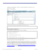
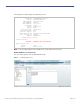
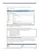
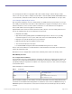
To define the Cisco Catalyst 3850, on the ISE screen, navigate to Administration Network Resources Network Devices as in Figure 2. Figure 2. Device Definition in ISE The dot1x needs to be enabled on the switch globally for wired and wireless clients. dot1x system-auth-control ! 802.1X Configuration for Wired Users 802.1X for wired users is configured per port.
class-map type control subscriber match-all DOT1X_NO_RESP match method dot1x ! policy-map type control subscriber DOT1X event session-started match-all 1 class always do-until-failure 2 authenticate using dot1x retries 3 retry-time 60 event authentication-success match-all event authentication-failure match-all 5 class DOT1X_NO_RESP do-until-failure 1 authentication-restart 60 ! 802.1X Configuration for Wireless Users For wireless clients, 802.1x is configured under WLAN configuration mode.
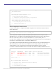
I - Awaiting IIF ID allocation P - Pushed Session (non-transient state) R - Removing User Profile (multi-line status for details) U - Applying User Profile (multi-line status for details) X - Unknown Blocker The following output shows the detailed view of the wireless client session: Switch#sh access-session mac b065.bdb0.a1ad details Interface: IIF-ID: MAC Address: Capwap0 0xE49A0000000008 b065.bdb0.a1ad IPv6 Address: Unknown IPv4 Address: 12.0.0.
The following is the detailed output of the wired client session: Switch#sh access-session mac 0024.7eda.6440 details Interface: GigabitEthernet1/0/13 IIF-ID: 0x1092DC000000107 MAC Address: 0024.7eda.6440 IPv6 Address: Unknown IPv4 Address: 10.3.0.113 User-Name: corp1 Status: Authorized Domain: DATA Oper host mode: single-host Oper control dir: both Session timeout: N/A Common Session ID: 0A010101000011334A316CE0 Acct Session ID: Unknown Handle: 0x8B00039F Current Policy: 802.
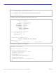
After defining ACL in ISE, it can be associated with an authorization profile, as shown in Figure 4. Figure 4. Note: Authorization Profile If a named authentication method-list is in place for AAA, an attribute needs to be set from ISE, as shown in 4 Method-List in this example is CLIENT_AUTH.
The total capacity of the ACEs is an aggregate number that constitutes all types of ACEs. One type of ACE, however, can scale up to 1500. For example, the total number of Port ACL (PACL) access control entries cannot exceed 1500. But a combination of PACL and Router ACL (RACL) access control entries can scale up to 3000. Cisco Catalyst 3850 Quality of Service One of the primary advantages of the Cisco Catalyst 3850 is the visibility into wireless packets at the access layer.
Unlike wired, wireless is considered untrusted on the Cisco Catalyst 3850. The default trust setting for wireless target is untrust: that is, the packets are marked down to 0 in the absence of SSID-based policy. The startup configuration on the Cisco Catalyst 3850 always has the following CLI: qos wireless-default-untrust This CLI is part of the default configuration (automatically created) and cannot be modified in the current release. That means the wireless will always be untrusted.
permit udp any any eq 1214 ip access-list extended SIGNALING remark SCCP permit tcp any any range 2000 2002 remark SIP permit tcp any any range 5060 5061 permit udp any any range 5060 5061 ip access-list extended TRANSACTIONAL-DATA remark HTTPS permit tcp any any eq 443 remark ORACLE-SQL*NET permit tcp any any eq 1521 permit udp any any eq 1521 The following is the configuration for creating a class-map for each application service and applying match statements: class-map match-any BULK-DATA match access-g
With table-maps, one can create a map of values that can be used between the same or different markings such as DSCP, CoS, and so on. The values that can be mapped are from 0 through 99 in decimal. Table-map also has a default mode of operation for values that do not have a mapping explicitly configured. If it is set to ignore, there will not be any change to the marking, unless an explicit mapping is configured. It can be configured to copy or to set a specific value.
Applying Ingress Policies Like other Cisco Catalyst platforms, Cisco Catalyst 3850 Switches offer two simplified methods to apply service policies. Depending on the deployment model, either of the following methods may be used: ● Port-based QoS: Applying service policy on a per-physical port basis will force traffic to pass through QoS policies before entering the network.
class-map CALL-SIG match dscp cs3 class-map CRITICAL-DATA match dscp af21 af22 af23 class-map VIDEO-STREAM match dscp af31 af32 af33 class-map Scavenger-Q match dscp cs1 After traffic is identified using DSCP, policy bases can be applied on classifications.
Wireless: Ingress Quality of Service Ingress Marking and Policing on Wireless Client In the ingress direction, traffic can be marked and policed at client level.
The applied policy can be shown with the following CLI: Switch# sh policy-map interface wireless client Client 000A.CC10.
If the policy name is downloaded from the ISE server, the server needs to be configured as shown in Figure 6, with the AV pair ip:sub-qos-policy-in=Standard-Employee. Figure 6. Authentication Profile The same policy can be applied for open wired ports as well. The policy needs to be attached to the port and not to the clients. Currently QoS policies cannot be attached to wired “clients.” Note: Wired port application is described earlier in the wired section.
table-map dscp2dscp default copy Policy-map TRUST Table Map dscp2dscp default copy The QoS policy is applied under the WLAN configuration. The SSID policy is applied as shown in the following example. This results in “trusted” behavior for traffic ingressing from wireless, similar to wired. wlan open 1 Employees service-policy input TRUST Wireless: Egress Quality of Service This explains the capabilities of QoS that are available on the Cisco Catalyst 3850.
The following is the default behavior of the four queues: Q0 (RT1): Control traffic Q1 (RT2): None Q2 (NRT): Everything other than multicast NRT and control traffic Q3 (multicast NRT): Multicast and nonclient traffic Default QoS policy is applied to the wireless port in the downstream (egress) direction. On port level no policy is supported in upstream (ingress) direction. The policy on the port is applied to the CAPWAP encapsulated packets egressing out to the access point.
bandwidth remaining ratio 10 Class-map: class-default (match-any) Match: any (total drops) 0 (bytes output) 0 The “port_child_policy” can be modified by the user to queue different application traffic at the SSID level. This traffic is queued toward the appropriate queues at the port level. The following is the “port_child_policy” configuration example: Switch#sh run policy-map port_child_policy Building configuration...
Match: any shape (average) cir 200000000, bc 800000, be 800000 target shape rate 200000000 Radio dot11a iifid: 0x104F10000000011.0xCF8F4000000005 Service-policy output: def-11an Class-map: class-default (match-any) Match: any shape (average) cir 400000000, bc 1600000, be 1600000 target shape rate 400000000 Although the preceding policy shows its shaping, it does not buffer or smooth out the rate. Essentially this is a rate limiter at radio level.
Policy-map guest-ssid Class class-default Shape average percent 20 On the enterprise SSID class-map voice and video, the policer enforces the aggregate unicast traffic at the BSSID level. The class default is configured to provide a minimum bandwidth allocation to the enterprise SSID, which is able to utilize the additional unused bandwidth in the absence of congestion.
Cisco Catalyst 3850 NetFlow Architecture (Wired and Wireless) NetFlow Cisco Catalyst 3850 Overview The Cisco Catalyst 3850 supports both ingress and egress FnF on all ports of the switch at line rate. Switch raw scalability is up to 24K cached flows, whereas it is 8K for ingress and 16K for egress per UADP ASIC. The Cisco Catalyst 3850 supports NetFlow Version 9, with IPv4, IPv6, Layer 2 flows, and sampled NetFlow. TCP flags are also exported as part of the flow information.
Configuring a Flow Record (Egress) flow record v4out match ipv4 protocol match ipv4 tos match ipv4 source address match ipv4 destination address match transport source-port match transport destination-port match interface output collect interface input collect transport tcp flags collect counter bytes long collect counter packets long collect timestamp absolute first collect timestamp absolute last collect counter bytes layer2 long Exporter/Collector Information There are two primary methods to access NetFl
flow monitor v4 exporter Collector exporter Collector 1 cache timeout active 60 cache timeout inactive 20 record v4 Attaching a Flow Monitor to Supported Port Types Wired Port interface GigabitEthernet1/0/1 description Interface for WIRED CLIENT in CONVERGED VLAN switchport access vlan 10 switchport mode access ip flow monitor v4 input ip flow monitor v4out output load-interval 30 no shutdown ! Wireless WLAN Port wlan SSID 1 SSID client vlan 12 ip flow monitor v4 input ip flow monitor v4out output no shutd
Flexible NetFlow Outputs To display the status and statistics for a flexible NetFlow flow monitor, use the “Show Flow monitor” command in privileged EXEC mode.
19:52:12.755 10.1.22.101 10.1.1.22 19:52:10.755 51524 5060 Gi1/0/3 LIIN0 1038 3 19:52:10.755 To display top N destination aggregated flow statistics from a flow monitor cache, use the following command. Switch# show flow monitor v4 cache aggregate ipv4 destination add sort counter bytes long top 4 Processed 4 flow Aggregated to 4 flow Showing the top 4 flow IPV4 DST ADDR flows bytes long pkts long ========== ==================== ==================== =============== 10.1.1.22 1 1038 3 10.1.
IPV6 SRC ADDR long IPV6 DST ADDR TRNS SRC PORT ============================================= TRNS DST PROT bytes long pkts ================== 2322::2 FF02::1:FF00:1 0 34560 58 72 1 2322::2 2201::2 1024 1026 17 9166290 43649 2322::2 2201::2 1024 1027 17 9166290 43649 2322::2 2201::2 1024 1024 17 9166500 43650 To display top N IPv6 destination address aggregated flow statistics from a flow monitor cache, use the following command: Switch# show flow monitor v6_m1 cache aggregat
Multicast Overview (Traditional and Converged Multicast) Efficient and intelligent use of bandwidth is paramount, particularly with the advent of video, mobility, and cloud technologies. It is also critical considering the surge in related one-to-many or many-to-many communicationbased applications. Multicast helps to fulfill the requirement of such bandwidth-intensive applications with its inherent ability to replicate a single stream when and where necessary.
The videostream mode is a further enhancement of the preceding. Instead of sending the multicast as broadcast at the lowest data rate, the access point converts the original multicast packet as unicast and sends it only to the interested client at the highest available data rate. This works the same way as it works in today’s Cisco Unified Wireless Network as the function is performed at the access point level.
Following is the basic configuration of wireless multicast: ● Configure IGMP snooping and querier: Switch(config)#ip igmp snooping Switch(config)#ip igmp snooping querier ● Configure wireless multicast and access point CAPWAP mode: Switch(config)#wireless multicast Switch(config)#ap capwap multicast 234.5.6.
To display all (S,V,G) list and the corresponding MGID value, use the “Show wireless multicast group summary” command in privileged EXEC mode. Switch#show wireless multicast group summary IPv4 groups ------------MGID Source Group Vlan ----------------------------------------------------------4160 0.0.0.0 239.255.67.250 412 4162 0.0.0.0 239.255.255.250 412 4163 0.0.0.0 224.0.1.
Group: 239.255.67.250 Vlan: 412 Source: 0.0.0.0 blacklisted: no SGV to Client mappings ---------------------Group: 224.0.1.60 Source: 0.0.0.0 Vlan: 412 Client: 10.33.170.101 Port: Ca10 Blacklisted: no Group: 239.255.67.250 Source: 0.0.0.0 Vlan: 412 Client: 10.33.170.75 Port: Ca1 Blacklisted: no Group: 239.255.255.250 Source: 0.0.0.0 Vlan: 412 Client: 10.33.170.75 Port: Ca1 Blacklisted: no Client: 10.155.156.
To display the multicast groups that are directly connected to the switch and that were learned through IGMP, use the “show ip igmp groups” command in privileged EXEC mode. Switch#show ip igmp groups IGMP Connected Group Membership Group Address Interface Uptime Expires Last Reporter 239.255.255.255 Vlan413 4d18h 00:02:42 10.32.104.1 239.255.255.255 Vlan412 4d18h 00:01:39 10.33.170.1 239.255.255.250 Vlan412 01:27:18 00:02:45 10.33.170.
To display the IP IGMP membership status of all multicast groups on a switch, use the “show ip igmp membership all” command in privileged EXEC mode.
Converged Access with the Cisco Catalyst 3850 The Cisco Catalyst 3850 Switch offers scalable, resilient, and future-proofed wired and wireless services. It serves as an integrated wireless LAN controller for up to 50 Cisco access points and 2000 clients per stack. The Cisco Catalyst 3850 can form the basis of a deployment in which the access points and clients can scale up to 250 Cisco access points and 16,000 clients, respectively.
The mobility controller’s area of responsibility lies in the mobility subdomain it controls. All the mobility agents in the subdomain form CAPWAP mobility tunnels to the mobility controller and report local and roamed client states to the mobility controller. The mobility controller builds a database of client stations across all the mobility agents.
Figure 8. Hierarchical Roles in Converged Access The SPGs are designed as a group of mobility agent switches to where the users frequently roam. It is important that roams within an SPG are local to the SPG and need not involve the mobility controller, whereas roams across an SPG require traffic to traverse the mobility controller.
Figure 9. Single Cisco Catalyst 3850 Stack for Wired/Wireless in Small Branch If the wireless deployment consists of only a Cisco Catalyst 3850 Switch running as a mobility controller with several other switches operating as mobility agents, 16 mobility agents can be grouped together in one SPG under one mobility controller. The access point and client scale remain at 50 Cisco access points and 2000 clients, as seen in Figure 10.
For medium campus wireless deployments scaling up to 250 Cisco access points and 16,000 clients, 7 mobility controller switches (with other mobility agent switches operating as mobility agents in their SPG) can be grouped together in a mobility group with guest access provided by guest anchor controller in the DMZ, as seen in Figure 11. If there is no guest access operational, 8 mobility controller switches can be grouped together in a mobility group. Figure 11.
Figure 12. 5508/WiSM2/5760 Controller Appliances with Cisco Catalyst 3850 Switches for Large Campus Configuring Converged Access with Cisco Catalyst 3850 This section explains how to configure the wireless services on the Cisco Catalyst 3850. Consider a large branch or a small campus that has a deployment scale of up to 250 access points and 16,000 clients that can be implemented only using Cisco Catalyst 3850 Switches.
The Cisco access points must be connected directly to the Cisco Catalyst 3850 Switch. One Cisco Catalyst 3850 Switch forms the access layer. The distribution in this example is made of the Cisco Catalyst 4500E Supervisor 7-E systems in virtual switching system (VSS) configuration. It is a multilayer network design in which the L3 SVI for L2 VLANs on the access is defined on the VSS system. The Cisco Catalyst 3850 connects to the VSS through a L2 port channel configured as an 802.
Relevant excerpts from outputs regarding wireless configuration on the Cisco Catalyst 3850 are shown in the following: MC1#show wireless mobility summary Mobility Controller Summary: Mobility Role : Mobility Controller Mobility Protocol Port : 16666 Mobility Group Name : default Controllers configured in the Mobility Domain: IP Public IP Group Name Multicast IP Link Status ----------------------------------------------------------------------------20.1.3.
Figure 14. Configuring Mobility Agents and Switch Peer Group on Cisco Catalyst 3850 In this case the additional Cisco Catalyst 3850 Switches can be added and configured as mobility agents with the previously configured switch acting as mobility controller. The mobility agents can be configured in one SPG. Relevant configurations to be done on the mobility controller are given in the following: wireless mobility controller peer-group SPG1 wireless mobility controller peer-group SPG1 member ip 20.1.5.
wireless mobility controller ip 20.1.3.2 public-ip 20.1.3.2 wireless management interface Vlan602 wlan Predator 1 Predator aaa-override client association limit 2000 client vlan 500 security wpa wpa2 ciphers tkip security dot1x authentication-list ise no shutdown ap cdp where 20.1.3.2 is the switch/wireless management IP address of the mobility controller switch, Vlan 602 is the switch/wireless management interface, and Vlan 500 is the client VLAN that is spanned across from the mobility controller switch.
Figure 15. Configuring Mobility Group on Multiple Mobility Controllers on Cisco Catalyst 3850 Assume that there was an acquisition of the company next door, and now the two networks have to be integrated in the current network. The network in the acquired company operates in routed access design mode, as shown by the diagram. The new switch can be configured to operate as a mobility agent under the previously defined mobility controller switch in the network.
Relevant configurations done on the MA3 switch in this case are given in the following: wireless mobility controller ip 20.1.3.2 public-ip 20.1.3.2 wireless management interface Vlan604 wlan Predator 1 Predator aaa-override client vlan 701 security wpa wpa2 ciphers tkip security dot1x authentication-list ise no shutdown ap cdp where 20.1.3.
These two mobility controller switches can be grouped together in one mobility group to enable fast roaming between clients of each respective subdomain. Relevant configuration that needs to be done on the existing mobility controller switch is as given in the following: wireless mobility group member ip 20.1.9.2 public-ip 20.1.9.2 group MG wireless mobility group name MG where MG is the mobility group name that is created, and 20.1.9.
Point of attachment (PoA) moves with user mobility and is defined as the access point to which the user joins or roams. There are two types of roams within the wireless network: intracontroller roams and intercontroller roams: ● Intracontroller roams occur when a user roams from one access point to another access point connected to the same controller.
The previous controller does not hold any state of the client that has roamed to another controller. In this case the client traffic is CAPWAP encapsulated by the access point and terminated at the new controller with which access point has associated. ● L3 roam occurs when the user roams from an access point connected to its controller to a different access point connected to another controller, where the two controllers are L3 adjacent to each other. (See Figure 18.) Figure 18.
Understanding Roams in Converged Access Since roams in Cisco Unified Wireless Network are explained earlier, this section explains the roams as they occur in converged access mode. It will be clear that the roams in converged access deployment are no different than those that occur in an existing Cisco Unified Wireless Network. In converged access deployment, QoS policies are applied at the foreign or PoA switch, and ACL policies are applied at the anchor or PoP switch.
There is a provision per WLAN that the administrator can configure, if they want a L2 roam like the Cisco Unified Wireless Network, where both the PoP and PoA of the user moves. This is the nontunneled (nonsticky) L2 roam. The advantage of this roam is that the roamed traffic does not need to be back-hauled to the PoP switch, since the PoP moves along with the user mobility.
Traffic Paths in Converged Access This section explains the traffic path (profile) for local and roamed wireless clients across the different SPGs and mobility controllers. (See Figure 21.) Figure 21. Client Roams Within an SPG in Converged Access As seen earlier, roams within an SPG are constrained within the anchor and foreign switches of the SPG. As mentioned before, traffic for wireless clients that roam across an SPG has to traverse a mobility controller.
Figure 22. Client Roams Across Mobility Controller in Converged Access In the preceding scenario, an intersubdomain (intermobility controller) roam is explained. The initial client join happens at MA1 in SPG1. The wireless traffic is terminated locally at MA1 and delivered to the wired side when the client is static. When the client roams to an access point connected to MC2, it roams from the subdomain whose master is MC1.
Table 3 is a list of switch names, IP addresses, their roles in SPG, and mobility group that form part of the example network. Understanding this will help explain the client roams as they roam from one switch to another. Table 3. Switch Roles and Other Details in Example Topology Switch Name IP Address Mobility Role Switch Peer Group Mobility Group MC1 20.1.3.2 Mobility controller - MG MA1 20.1.5.2 Mobility agent SPG1 MG MA2 20.1.7.2 Mobility agent SPG1 MG MA3 20.1.8.
Initial client join on MA1, as seen in CLI on the switch, where it shows the client MAC address, to which access point it is connected, and the WLAN and 11n on 5GHz: MA1#show wcdb database all Total Number of Wireless Clients = 2 Clients Waiting to Join = 0 Local Clients = 2 Anchor Clients = 0 Foreign Clients = 0 MTE Clients = 0 Mac Address VlanId IP Address Src If Auth Mob -------------- ------ --------------- ------------------ -------- ------b065.bdbf.77a3 500 20.1.1.
MC1#sh wireless mobility controller client summary Number of Clients : 2 State is the Sub-Domain state of the client. * indicates IP of the associated Sub-domain Associated Time in hours:minutes:seconds MAC Address State Anchor IP Associated IP Associated Time ------------------------------------------------------------------------------b065.bdb0.a1ad Local 0.0.0.0 20.1.5.2 00:00:23 b065.bdbf.77a3 Local 0.0.0.0 20.1.5.2 00:00:35 Notice the anchor IP 0.0.0.
The following are the relevant outputs displaying the client roam. In this case, MA1 becomes the anchor switch, while MC1 becomes the foreign switch. MC1#show wireless client summary Number of Local Clients : 2 MAC Address AP Name WLAN State Protocol -------------------------------------------------------------------------------b065.bdb0.a1ad 3602I_G2/0/1_3A04 1 UP 11n(5) b065.bdbf.
Comparing the preceding output with the one in the initial client join, notice that the access point name changes to the switch IP address to where the clients roamed (switch/wireless management IP address of MC1 in this case), and the protocol state becomes “Mobile.
where the mobility state is “anchor,” and the access point name is the switch/wireless management IP address of the foreign switch (MC1): 20.1.3.2. (See Figure 25.) Figure 25. Client Roams Across SPG in Converged Access In the preceding scenario the endpoints roam from the mobility controller to another mobility agent in SPG2. The thing to note here is that this is an L3 roam, since the client wireless VLAN 500 is not spanned across to this mobility agent.
Mac Address VlanId IP Address Src If Auth Mob -------------- ------ --------------- ------------------ -------- ------b065.bdbf.77a3 701 20.1.1.53 0x00C9D9C000000004 RUN FOREIGN b065.bdb0.a1ad 701 20.1.1.52 0x00C9D9C000000004 RUN FOREIGN Since the roam is across an SPG, the mobility controller gets involved in the mobility in this case.
Mac Address VlanId IP Address Src If Auth Mob -------------- ------ --------------- ------------------ -------- ------b065.bdbf.77a3 500 20.1.1.53 0x00D03BC000000002 RUN ANCHOR b065.bdb0.a1ad 500 20.1.1.52 0x00D03BC000000002 RUN ANCHOR Figure 26 shows client roam across MCs Figure 26.
Total Number of Wireless Clients = 2 Clients Waiting to Join = 0 Foreign Clients = 2 MTE Clients = 0 Mac Address VlanId IP Address Src If Auth Mob -------------- ------ --------------- ------------------ -------- ------b065.bdbf.77a3 702 20.1.1.53 0x00C33C0000000004 RUN FOREIGN b065.bdb0.a1ad 702 20.1.1.52 0x00C33C0000000004 RUN FOREIGN MC2#show wireless client mac b065.bdbf.77a3 detail Client MAC Address : b065.bdbf.77a3 Client Username : blackbird AP MAC Address : 8875.56da.
wlan Predator shutdown no mobility anchor sticky no shutdown Tracking the initial client join on MA1: MA1#show wireless client summary Number of Local Clients : 2 MAC Address AP Name WLAN State Protocol -------------------------------------------------------------------------------b065.bdb0.a1ad 3602I_G1/0/1_66BC 1 UP 11n(5) b065.bdbf.
MA1#show wcdb database all Total Number of Wireless Clients = 0 Mac Address VlanId IP Address Src If Auth Mob -------------- ------ --------------- ------------------ -------- ------The switch where the clients initially joined has 0 clients after the roam, as seen earlier. MA2#show wireless client summary Number of Local Clients : 2 MAC Address AP Name WLAN State Protocol -------------------------------------------------------------------------------b065.bdb0.a1ad AP6073.5c90.
Tunnel Roles in Converged Access This section explains what function each CAPWAP tunnel plays in the converged access deployment.
Ca5 3502E_G2/0/25_83A9 data Gi2/0/25 unicast - Ca4 3602I_G2/0/1_3A04 data Gi2/0/1 unicast - Name SrcIP SrcPort DestIP DstPort DtlsEn MTU ------ --------------- ------- --------------- ------- ------ ----Ca1 20.1.3.2 16667 20.1.5.2 16667 No 1464 Ca2 20.1.3.2 16667 20.1.7.2 16667 No 1464 Ca3 20.1.3.2 16667 20.1.8.2 16667 No 1464 Ca0 20.1.3.2 16667 20.1.9.2 16667 No 1464 Ca5 20.1.3.2 5247 20.1.3.54 63548 No 1657 Ca4 20.1.3.2 5247 20.1.3.
Field L2 In L2 Out IPv4 In IPV4 Out IPv6 In IPv6 Out mac source address output - - - - - - Notes mac destination address input Yes - Yes - Yes - mac destination address output - Yes - Yes - Yes ipv4 version - - Yes Yes Yes Yes ipv4 tos - - Yes Yes Yes Yes ipv4 protocol - - Yes Yes Yes Yes ipv4 ttl - - Yes Yes Yes Yes ipv4 version - - Yes Yes Yes Yes Same as IP_VERSION ipv4 tos - - Yes Yes Yes Yes Same as IP_TOS ipv4 ttl - - Yes Yes
Printed in USA © 2013 Cisco and/or its affiliates. All rights reserved. This document is Cisco Public Information.