C H A P T E R 5 Installing Memory in the Router This chapter describes procedures for adding and replacing memory in Cisco 3600 series routers, and contains the following sections: Warning Caution Note • Accessing the Mainboard, page 5-2 • Replacing DRAM and SDRAM, page 5-6 • Replacing Flash Memory SIMMs, page 5-19 • Replacing the ROM, page 5-24 • Closing the Router, page 5-29 • Installing and Configuring Flash Memory Cards in Cisco 3620, Cisco 3640, and Cisco 3660 Routers, page 5-34 • In
Chapter 5 Installing Memory in the Router Accessing the Mainboard Accessing the Mainboard This section describes how to open the system in order to access the router’s internal components such as memory modules and the ROM. You need a number 2 Phillips or flat-blade screwdriver to perform this procedure. Warning Do not touch the power supply when the power cord is connected.
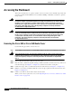
Chapter 5 Installing Memory in the Router Accessing the Mainboard Figure 5-1 Removing the Cisco 3620 Router Cover Screw SY ST EM RP H7241 S CO N AU X AC TIV 0 1 RE E AD Y PC 1 0 MC IA Figure 5-2 Removing the Cisco 3640 Router Cover Screw SY ST EM RP H7043 S CO N AU X AC TIV 0 1 2 RE E 3 AD Y 1 PC MC IA 0 Removing the Cisco 3631 Router Cover Perform the following procedure to remove the chassis cover: Step 1 Power OFF the router.
Chapter 5 Installing Memory in the Router Accessing the Mainboard Warning Before opening the chassis, disconnect the telephone-network cables to avoid contact with telephone-network voltages. To see translations of the various warnings that appear in this publication, refer to the Regulatory Compliance and Safety Information document that accompanied this device. Step 2 Disconnect all network interface cables from the rear panel. Step 3 Place the router on a flat surface.
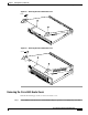
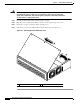
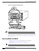
Chapter 5 Installing Memory in the Router Accessing the Mainboard Removing the Cisco 3660 Mainboard Tray Note In this publication, references to Cisco 3660 routers include both Cisco 3661 and Cisco 3662 models. Use the following procedure to remove the mainboard tray: Step 1 Warning Power OFF the router. However, to channel ESD voltages to ground, do not unplug the power cable. Before opening the chassis, disconnect the telephone-network cables to avoid contact with telephone-network voltages.
Chapter 5 Installing Memory in the Router Replacing DRAM and SDRAM Figure 5-4 Removing the Cisco 3660 Mainboard Tray 1 VCC OK SYSTEM FDX LINK 100Mbps FDX LINK 100Mbps 1 0 SEE MANUAL BEFORE INSTALLATION 0 RC HS RD EN TC LB/CN V0 TD V1 1 HIGH SPEED SERIAL 1HSSI IN USE VIC FXS IN USE VOICE 2V SERIAL 4T ETHERNET 4E SERIAL 3 SERIAL 2 SERIAL 1 SERIAL 0 ETH 3 ETH 2 ETH 1 3 2 1 CN/LP RXC 0 ETH 0 LINK RXD TXC TXD CN/LP RXC RXD TXC TXD CN/LP RXC EN RXD TXC TXD CN/LP RXC
Chapter 5 Installing Memory in the Router Replacing DRAM and SDRAM DRAM SIMMs (Used in Cisco 3620 and Cisco 3640 Routers) This section describes how to upgrade DRAM single in-line memory modules (SIMMs) in Cisco 3620 and Cisco 3640 routers. You might need to upgrade the DRAM SIMMs for the following reasons: • You upgraded the Cisco IOS feature set or release and it requires additional DRAM.
Chapter 5 Installing Memory in the Router Replacing DRAM and SDRAM Figure 5-5 DRAM SIMM Locations in the Cisco 3620 Router 1 2 3 H7317 0 DRAM SIMMs Figure 5-6 DRAM SIMM Locations in the Cisco 3640 Router 1 2 3 H7081 0 DRAM SIMMs Cisco 3600 Series Hardware Installation Guide 5-8 OL-2056-02
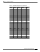
Chapter 5 Installing Memory in the Router Replacing DRAM and SDRAM Table 5-1 32-Bit DRAM Configuration for Cisco 3620 Routers Bank 0 (SIMM 0) Bank 1 (SIMM 1) Bank 2 (SIMM 2) Bank 3 (SIMM 3) Total Memory 4 MB 4 MB 4 MB 4 MB 16 MB 4 MB 4 MB 8 MB Not installed 16 MB 8 MB 8 MB Not installed Not installed 16 MB 16 MB Not installed Not installed Not installed 16 MB 4 MB 16 MB Not installed Not installed 20 MB 4 MB 4 MB 4 MB 4 MB 8 MB 8 MB 4 MB Not installed 20 MB 16 MB 4 MB Not
Chapter 5 Installing Memory in the Router Replacing DRAM and SDRAM Table 5-2 32-Bit DRAM Configuration for Cisco 3640 Routers Bank 0 (SIMM Bank 1 0) (SIMM 1) Bank 2 (SIMM 2) Bank 3 (SIMM 3) 4 MB 4 MB 8 MB Not installed 16 MB 16 MB Not installed Not installed Not installed 16 MB 4 MB 16 MB Not installed Not installed 20 MB 8 MB 8 MB 4 MB 16 MB 4 MB Not installed Not installed 20 MB 8 MB 16 MB Not installed Not installed 24 MB 8 MB 8 MB 8 MB 16 MB 8 MB Not installed Not installe
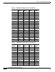
Chapter 5 Installing Memory in the Router Replacing DRAM and SDRAM Table 5-3 64-Bit DRAM Configuration for Cisco 3640 Routers (continued) Bank 0 (SIMM 0) Bank 1 (SIMM 1) Bank 2 (SIMM 2) Bank 3 (SIMM 3) Total Memory 16 MB 16 MB 8 MB-Dual 8 MB-Dual 48 MB 16 MB 16 MB 16 MB 16 MB 64 MB 32 MB-Dual3 32 MB-Dual Not installed Not installed 64 MB 32 MB-Dual 32 MB-Dual 4 MB 4 MB 72 MB 32 MB-Dual 32 MB-Dual 8 MB 8 MB 80 MB 32 MB-Dual 32 MB-Dual 8 MB-Dual 8 MB-Dual 80 MB 32 MB-Dual 32 MB
Chapter 5 Installing Memory in the Router Replacing DRAM and SDRAM Removing DRAM SIMMS Perform this procedure to remove DRAM SIMMs: Step 1 Attach an ESD-preventive wrist strap and ensure that it makes good contact with your skin. Connect the equipment end of the wrist strap to the metal back plate of the chassis, avoiding contact with the connectors. Step 2 On the mainboard, locate the DRAM SIMM sockets shown in Figure 5-5 or Figure 5-6. Caution Step 3 Handle SIMMs by the non-connector edges only.
Chapter 5 Installing Memory in the Router Replacing DRAM and SDRAM Installing DRAM SIMMs Perform this procedure to install DRAM SIMMs: Step 1 Attach an ESD-preventive wrist strap and ensure that it makes good contact with your skin. Connect the equipment end of the wrist strap to the metal back plate of the chassis, avoiding contact with the connectors. Step 2 On the mainboard, locate the DRAM SIMM sockets shown in Figure 5-5 or Figure 5-6. Caution Handle SIMMs by the edges only.
Chapter 5 Installing Memory in the Router Replacing DRAM and SDRAM SDRAM DIMMs Used in the Cisco 3631 and Cisco 3660 Router This section describes how to upgrade synchronous dynamic random access memory (SDRAM) dual in-line memory modules (DIMMs) in the Cisco 3631 and Cisco 3660 routers. You might need to upgrade the SDRAM DIMMs for the following reasons: • You upgraded the Cisco IOS feature set or release and it requires additional SDRAM.
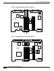
Chapter 5 Installing Memory in the Router Replacing DRAM and SDRAM Figure 5-10 SDRAM DIMM Locations in the Cisco 3631 Router SDRAM DIMMs 62578 0 1 Table 5-4 SDRAM Configurations for Cisco 3631 Routers Bank 0 (SIMM 0) Bank 1 (SIMM 1) Total Memory 64 MB Not installed 64 MB 32 MB 32 MB 64 MB 32 MB 64 MB 96 MB 64 MB 32 MB 96 MB 128 MB Not installed 128 MB 64 MB 64 MB 128 MB Not installed 128 MB 128 MB 32 MB 128 MB 160 MB 128 MB 32 MB 160 MB 64 MB 128 MB 192 MB 128 MB 64
Chapter 5 Installing Memory in the Router Replacing DRAM and SDRAM Figure 5-11 SDRAM DIMM Locations in the Cisco 3660 Router 17337 SDRAM DIMMs 0 Table 5-5 1 SDRAM Configurations for Cisco 3660 Routers Bank 0 (SIMM 0) Bank 1 (SIMM 1) Total Memory 16 MB 16 MB 32 MB 32 MB Not installed 32 MB 32 MB 16 MB 48 MB 32 MB 32 MB 64 MB 64 MB Not installed 64 MB 64 MB 16 MB 80 MB 64 MB 32 MB 96 MB 64 MB 64 MB 128 MB 128 MB Not installed 128 MB 128 MB 16 MB 144 MB 128 MB 32 MB
Chapter 5 Installing Memory in the Router Replacing DRAM and SDRAM SDRAM DIMM Orientation DIMMs have polarization notches to ensure proper orientation and alignment holes to ensure proper positioning. Figure 5-12 shows the polarization notches and alignment holes on a DIMM. Caution To avoid damaging ESD-sensitive components, observe all ESD precautions. To avoid damaging the underlying mainboard, do not use excessive force when you remove or replace DIMMs.
Chapter 5 Installing Memory in the Router Replacing DRAM and SDRAM Removing SDRAM DIMMS Perform this procedure to remove SDRAM DIMMs: Step 1 Attach an ESD-preventive wrist strap and ensure that it makes good contact with your skin. Connect the equipment end of the wrist strap to the metal back plate of the chassis, avoiding contact with the connectors. Step 2 On the mainboard, locate the SDRAM DIMM sockets shown in Figure 5-11. Caution Step 3 Handle DIMMs by the edges only.
Chapter 5 Installing Memory in the Router Replacing Flash Memory SIMMs Installing SDRAM DIMMs Perform this procedure to install SDRAM DIMMs: Step 1 Attach an ESD-preventive wrist strap and ensure that it makes good contact with your skin. Connect the equipment end of the wrist strap to the metal back plate of the chassis, avoiding contact with the connectors. Step 2 On the mainboard, locate the SDRAM DIMM sockets shown in Figure 5-11. Caution Handle DIMMs by the non-connector edges only.
Chapter 5 Installing Memory in the Router Replacing Flash Memory SIMMs Table 5-6 Flash Memory SIMM Configurations Bank 0 Bank 1 Total Memory 4 MB – 4 MB 4 MB 4 MB 8 MB 4 MB 8 MB 12 MB 4 MB 16 MB 20 MB 8 MB – 8 MB 8 MB 4 MB 12 MB 8 MB 8 MB 16 MB 8 MB 16 MB 24 MB 16 MB – 16 MB 16 MB 4 MB 20 MB 16 MB 8 MB 24 MB 16 MB 16 MB 32 MB 32 MB 32 MB 64 MB1 1. The 64 MB configuration is only available on the Cisco 3660 router.
Chapter 5 Installing Memory in the Router Replacing Flash Memory SIMMs Figure 5-14 Flash Memory SIMM Locations on the Cisco 3620 Mainboard 0 H7318 1 Flash memory SIMMs Figure 5-15 Flash Memory SIMM Locations on the Cisco 3640 Mainboard 0 H7082 1 Flash memory SIMMs Cisco 3600 Series Hardware Installation Guide OL-2056-02 5-21
Chapter 5 Installing Memory in the Router Replacing Flash Memory SIMMs Figure 5-16 Flash Memory SIMM Locations on the Cisco 3660 Mainboard 17340 Flash memory SIMMs 0 1 Removing Flash Memory SIMMs Perform this procedure to remove a Flash memory SIMM from a mainboard: Step 1 Attach an ESD-preventive wrist strap and ensure that it makes good contact with your skin. Connect the equipment end of the wrist strap to the metal back plate of the chassis, avoiding contact with the connectors.
Chapter 5 Installing Memory in the Router Replacing Flash Memory SIMMs Figure 5-17 Removing Flash Memory SIMMs Top view 1. Pull the locking spring clips outward. 2. Push the top of the SIMM forward and down. SIMM polarization notch H7085 Front of chassis Installing Flash Memory SIMMs Perform this procedure to install Flash memory SIMMs: Step 1 Locate the Flash memory SIMM sockets on the mainboard. (See Figure 5-14 through Figure 5-16.) Caution Handle SIMMs by the non-connector edges only.
Chapter 5 Installing Memory in the Router Replacing the ROM Figure 5-18 Inserting Flash Memory SIMMs View from front of chassis 1. Insert the SIMM into the socket at an angle from vertical. 2. Push the top of the SIMM down and back. H7084 3. The socket guide posts fit through the holes in the SIMM. 4. The locking springs clip the back of the SIMM. Caution It is normal to feel some resistance, but do not use excessive force on the SIMM and do not touch the surface components to avoid damaging them.
Chapter 5 Installing Memory in the Router Replacing the ROM Follow this procedure to replace the ROM: Step 1 Attach an ESD-preventive wrist strap and ensure that it makes good contact with your skin. Connect the equipment end of the wrist strap to the metal backplane of the chassis, avoiding contact with the connectors.
Chapter 5 Installing Memory in the Router Replacing the ROM Figure 5-20 ROM Location on the Cisco 3640 Mainboard H7083 ROM Figure 5-21 ROM Location on the Cisco 3660 Mainboard 17341 ROM Step 4 If you have a Cisco 3620 or Cisco 3640 router, gently remove the old ROM with a ROM extraction tool or a small flat-blade screwdriver, and set it aside. If you have a Cisco 3660 router, gently remove the old ROM with a 32-pin PLCC extractor, and set it aside. (See Figure 5-22.
Chapter 5 Installing Memory in the Router Replacing the ROM Figure 5-22 Removing the ROM from the Cisco 3660 Mainboard PLCC extraction tool Angled tips Extraction slots PLCC extraction slot PLCC extraction slot ROM socket 14624 ROM Step 5 For a Cisco 3620 or Cisco 3640 router, orient and insert the new ROM in its socket (shown in Figure 5-19 and Figure 5-20), being careful to not bend or crush any of the bottom pins. To straighten out a bent pin, use needlenose pliers.
Chapter 5 Installing Memory in the Router Replacing the ROM Caution The notch on the ROM must match the notch on the mainboard socket. Installing the ROM backward will damage the ROM, the router, or both. When you finish replacing the ROM and have installed all internal components, proceed to: • Replacing the Cover on a Cisco 3620 or Cisco 3640 Router, page 5-30 • Replacing the Cisco 3660 Mainboard Tray, page 5-33 Testing ROM Installation Test your installation by rebooting the router.
Chapter 5 Installing Memory in the Router Closing the Router Copyright (c) 2001 by cisco Systems, Inc. c3745 processor with 131072 Kbytes of main memory Main memory is configured to 64 bit mode with parity disabled Upgrade ROMMON initialized Step 2 Reboot the router using the new ROM image: Router # reload This command will reload the router. Continue? [yes/no]: y Step 3 Verify the ROM version: Router # show rom-monitor ReadOnly ROMMON version: System Bootstrap, Version 12.
Chapter 5 Installing Memory in the Router Closing the Router Replacing the Cover on a Cisco 3620 or Cisco 3640 Router This section describes how to replace the router cover. You need a number 2 Phillips screwdriver to perform this procedure: Step 1 Place the chassis so the front panel faces you. Step 2 Hold the cover so the tabs at the rear of the cover are aligned with the chassis bottom. (See Figure 5-24 or Figure 5-25.
Chapter 5 Installing Memory in the Router Closing the Router Step 3 Push the cover toward the rear, making sure that the cover tabs fit under the chassis back panel, and the back panel tabs fit under the top cover. Step 4 Lower the front of the cover onto the chassis, making sure that the side tabs on the cover fit inside the chassis side panels, and the chassis tabs fit under the cover side panels.
Chapter 5 Installing Memory in the Router Closing the Router Figure 5-26 Replacing the Cisco 3631 Router Cover 1 62491 2 1 Insert tabs and slide cover Step 4 Reinstall the cover screws. Step 5 Reinstall the chassis on a rack or desktop. Step 6 Reconnect network interface cables. Step 7 Power ON the router.
Chapter 5 Installing Memory in the Router Closing the Router Replacing the Cisco 3660 Mainboard Tray This section describes how to replace the mainboard tray. You need a number 2 Phillips screwdriver to perform this procedure: Step 1 Place the chassis so the rear panel faces you. Step 2 Hold the tray so that the tabs at the tray’s lower corners are aligned with the ledge in the chassis opening. (See part 1 of Figure 5-27.
Chapter 5 Installing Memory in the Router Installing and Configuring Flash Memory Cards in Cisco 3620, Cisco 3640, and Cisco 3660 Routers Step 5 Tighten the two captive screws previously loosened in Step 3 of the “Removing the Cisco 3660 Mainboard Tray” section on page 5-5. (See part 4 in Figure 5-27.) Step 6 Reinstall the chassis on a rack or desktop. Step 7 Reconnect network interface cables. Step 8 Power ON the router. If the router does not power on, see Appendix A, “Troubleshooting.
Chapter 5 Installing Memory in the Router Installing and Configuring Flash Memory Cards in Cisco 3620, Cisco 3640, and Cisco 3660 Routers Perform this procedure to install a Flash memory card: Step 1 Verify that the Flash memory card’s write-protect switch is OFF. The write-protect switch is at the top left edge of the card, when you view it with the label side toward you. (See Figure 5-28.
Chapter 5 Installing Memory in the Router Installing and Configuring Flash Memory Cards in Cisco 3620, Cisco 3640, and Cisco 3660 Routers Figure 5-29 Installing a Flash Memory Card in a Cisco 3620 or Cisco 3640 Router PCMCIA slots H8625 1 0 Flash memory card Figure 5-30 Installing a Flash Memory Card in a Cisco 3660 Router PCMCIA slots Slot buttons 2 23786 1 Cisco 3600 Series Hardware Installation Guide 5-36 OL-2056-02
Chapter 5 Installing Memory in the Router Installing and Configuring Flash Memory Cards in Cisco 3620, Cisco 3640, and Cisco 3660 Routers Removing a Flash Memory Card Caution Do not remove the Flash memory card while it is performing a read or write operation, because the router will shut down. Perform this procedure to remove a Flash memory card: Step 1 On Cisco 3620 and Cisco 3640 routers, grasp the card near the slot and pull it straight out. (See Figure 5-31.
Chapter 5 Installing Memory in the Router Installing and Configuring Flash Memory Cards in Cisco 3620, Cisco 3640, and Cisco 3660 Routers Figure 5-32 Removing a Flash Memory Card from a Cisco 3660 Router PCMCIA slots 23787 Slot buttons 1 2 Partitioning a Flash Memory Card Flash memory cards ordered from Cisco Systems ship blank (without software installed). Before copying files to a Flash memory card, you might want to partition it.
Chapter 5 Installing Memory in the Router Installing and Configuring Flash Memory Cards in Cisco 3620, Cisco 3640, and Cisco 3660 Routers Displaying the Contents of a Flash Memory Card To display the contents of a Flash memory card, enter the show {slot0: | slot1:} command, for example: Router# show slot1: PCMCIA Slot1 flash directory, partition 1: File Length Name/status 1 1933052 c3640-i-mz.111-6.3.
Chapter 5 Installing Memory in the Router Installing and Configuring Flash Memory Cards in Cisco 3620, Cisco 3640, and Cisco 3660 Routers Step 3 Press Return or type y to erase the current contents of the partition, or enter n to save the contents. Then confirm your selection: Copy 'TESTFILE' from flash: device as 'TESTFILE' into slot0: device WITHOUT erase? [yes/no] y ! [OK - 68/4194304 bytes] Flash device copy took 00:00:05 [hh:mm:ss] Verifying checksum...
Chapter 5 Installing Memory in the Router Installing and Configuring Flash Memory Cards in Cisco 3620, Cisco 3640, and Cisco 3660 Routers Copying a File from a Flash Memory Card to System Flash Memory You can copy files from a Flash memory card to system (onboard) Flash memory (for instance, when restoring a backup).
Chapter 5 Installing Memory in the Router Installing and Configuring Flash Memory Cards in Cisco 3620, Cisco 3640, and Cisco 3660 Routers Step 4 Enter the copy {slot0: | slot1:}[partition:filename]{slot0: | slot1:} [partition:filename] command to copy a file from one slot to the other.
Chapter 5 Installing Memory in the Router Installing and Configuring Flash Memory Cards in Cisco 3620, Cisco 3640, and Cisco 3660 Routers Step 3 Enter the boot system flash {slot0: | slot1:}[partition:filename] command to specify the boot image location and name. In the following example, the boot image is located on the Flash memory card in the 0 slot, partition 3, and the filename is new.image: Router(config)# no boot system Router(config)# boot system flash slot0:3:new.
Chapter 5 Installing Memory in the Router Installing and Formatting Compact Flash Memory Cards in Cisco 3631 Routers Installing and Formatting Compact Flash Memory Cards in Cisco 3631 Routers This section describes how to install Compact Flash memory cards in Cisco 3631 routers, how to format the cards into a Class B Flash file system (low end file system) or a Class C Flash file system (similar to DOS), and how to perform file and directory operations in each file system.
Chapter 5 Installing Memory in the Router Installing and Formatting Compact Flash Memory Cards in Cisco 3631 Routers Compact Flash Memory Card Installation and Removal Perform the procedure below for installing or removing a Compact Flash memory card mounted internally on the router CPU/mainboard. To access the internal Compact Flash memory card, you need to remove the chassis cover. Removing the Chassis Cover This section describes how to remove the chassis cover to access the Compact Flash memory card.
Chapter 5 Installing Memory in the Router Installing and Formatting Compact Flash Memory Cards in Cisco 3631 Routers Figure 33 Removing the Cover from a Cisco 3631 2 62483 1 1 Lift cover 2 Slide cover Removing the Compact Flash Memory Card After removing the chassis cover as described in the “Removing the Cisco 3631 Router Cover” section on page 5-3, perform the following steps to remove the Compact Flash memory card from the router: Step 1 Locate the Compact Flash memory card on the CPU/mainbo
Chapter 5 Installing Memory in the Router Installing and Formatting Compact Flash Memory Cards in Cisco 3631 Routers Figure 34 Compact Flash Memory Card Location in a Cisco 3631 Compact Flash memory card 62479 Retention screw Step 2 Remove the retention screw that retains the Compact Flash memory card by using the Phillips screwdriver; save the retention screw for reinstallation. Step 3 Carefully pull the Compact Flash memory card free from the connector.
Chapter 5 Installing Memory in the Router Installing and Formatting Compact Flash Memory Cards in Cisco 3631 Routers Reinstalling the Cover Caution Before reinstalling the cover on the router, make sure that all cables are securely tucked in and are not in danger of being pinched or cut. This section describes how to reinstall the router cover. You need a number 2 Phillips screwdriver or flat blade screwdriver to perform this procedure: Step 1 Place the chassis on a flat surface.
Chapter 5 Installing Memory in the Router Installing and Formatting Compact Flash Memory Cards in Cisco 3631 Routers Step 4 Reinstall the cover screws. Step 5 Reinstall the chassis on a rack or desktop. Step 6 Reconnect network interface cables. Step 7 Power ON the router. Warning After wiring the DC power supply, remove the tape from the circuit breaker switch handle and reinstate power by moving the handle of the circuit breaker to the ON position.
Chapter 5 Installing Memory in the Router Installing and Formatting Compact Flash Memory Cards in Cisco 3631 Routers Base FAT Sector Base Data Sector 128 184 Please use "dir" command to display the contents of the card.
Chapter 5 Installing Memory in the Router Installing and Formatting Compact Flash Memory Cards in Cisco 3631 Routers eeeeeeeeeeeeeeeeeeeeeeeeeeeeeeeeeeeeeeeeeeeeeeeeeeeeeeeeeeeeeeeeeeeeeeeeeeeeeeeeeeeeeeeeee eeeeeeeeeeeeeeeeeeeeeeeeeeeeeeeeeeeeeeeeeeeeeeeeeeeeeeeeeeeeeeeeeeeeeeeeeeeeeeeeeeeeeeeeee eeeeeeeeeeeeeeeeeeeeeeeeeeeeeeeeeeeeeeeeeeeeeeeeeeeeeeeeeeeeeeeeeeeeeeeeeeeeeeeeeeeeeeeeee eeeeeeeeeeeeeeeeeeeeeeeeeeeeeeeeeeeeeeeeeeeeeeeeeeeeeeeeeeeeeeeeeeeeeeeeeeeeeeeeeeeeeeeeee eeeeeeeeeeeeeeeeeeeeeeeeeeeee
Chapter 5 Installing Memory in the Router Installing and Formatting Compact Flash Memory Cards in Cisco 3631 Routers Display the Contents of a Compact Flash Card To display the contents (directories and files) of a Compact Flash memory card formatted with a Class C Flash file system, use the dir flash: command.
Chapter 5 Installing Memory in the Router Installing and Formatting Compact Flash Memory Cards in Cisco 3631 Routers Rename a File in Flash To rename a file in a Compact Flash memory card, use the rename flash: original-filename flash: new-filename command. The following example shows output for renaming a Cisco IOS file in an internal Compact Flash memory card: Router# dir flash: Directory of flash:/ 3 1580 -rw-rw- 6458388 6462268 Mar 01 1993 00:00:58 Mar 06 1993 06:14:02 c3725-i-mz.tmp c3725-i-mz.
Chapter 5 Installing Memory in the Router Installing and Formatting Compact Flash Memory Cards in Cisco 3631 Routers Directory Operations Create a New Directory To create a directory in Compact Flash memory, use the mkdir flash:/directory-name command.
Chapter 5 Installing Memory in the Router Installing and Formatting Compact Flash Memory Cards in Cisco 3631 Routers Enter a Directory and Determine Which Directory You Are In To enter a directory in Compact Flash memory, use the cd flash:/directory-name command. To determine which directory you are in, use the pwd command. If you enter only cd, the router will enter the default home directory, which is flash:/.
Chapter 5 Installing Memory in the Router Installing and Formatting Compact Flash Memory Cards in Cisco 3631 Routers The following example shows output for copying a configuration file to the running configuration in an internal Compact Flash memory card (flash:): Router# copy flash:my-config2 running-config Destination filename [running-config]? 709 bytes copied in 0.
Chapter 5 Installing Memory in the Router Installing and Formatting Compact Flash Memory Cards in Cisco 3631 Routers The following example shows output for deleting a Cisco IOS file from a Compact Flash memory card, and then releasing the memory space originally occupied by the file: Router# dir flash: Directory of flash:/ 1 2 -rw-rw- 6458208 6458208 c3725-i-mz.tmp c3725-i-mz 16056320 bytes total (3139776 bytes free) Router# delete flash:c3725-i-mz.tmp Delete filename [c3725-i-mz.
Chapter 5 Installing Memory in the Router Installing and Formatting Compact Flash Memory Cards in Cisco 3631 Routers Cisco 3600 Series Hardware Installation Guide 5-58 OL-2056-02