
Bridge/Router Installation and Configuration Guide

2-27
Cisco 12016, Cisco 12416, and Cisco 12816 Router Installation and Configuration Guide
OL-11495-01
Chapter 2 Preparing for Installation
GRP Port Connection Guidelines
Caution To maintain Class B EMI compliance, you must use shielded cables when
connecting to the auxiliary and console ports of original GRPs (part numbers
GRP= and GRP-B=). An updated version of the GRP-B= board (Rev. F0) does not
require shielded cables for Class B compliance.
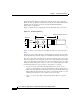
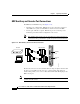
GRP Auxiliary Port Signals
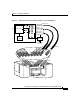
The GRP auxiliary port is a DB-25 DTE port for connecting a modem or other
DCE device to the router. The auxiliary port supports hardware flow control and
modem control.
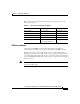
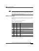
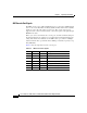
Table 2-2 lists the signals used on the auxiliary port.
Ta b l e 2-2 GRP Auxiliary Port Signals
Pin Signal Direction Description
1 GND — Shield ground
2 TxD Output Transmit data (to DCE)
3 RxD Input Receive data (from DCE)
4 RTS Output Request to send
(used for hardware flow control)
5 CTS Input Clear to send (used for hardware flow control)
6 DSR Input Data set ready
7 GND — Signal ground
8 DCD Input Carrier detect (used for modem control)
20 DTR Output Data terminal ready (used for modem control
only)
22 RING Input Ring