
Bridge/Router Installation and Configuration Guide


7-83
Cisco 12016, Cisco 12416, and Cisco 12816 Router Installation and Configuration Guide
OL-11495-01
Chapter 7 Maintaining the Router
Removing and Replacing Cards from the Chassis
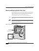
Use the following procedure to remove and replace an alarm card from either the
top or bottom card cage.
Caution To ensure proper alarm card screw alignment, line card slots adjacent to the alarm
cards must always be populated.
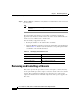
Step 1 Disconnect any cables from the alarm card.
Step 2 Remove the alarm card:
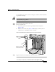
a. Loosen the captive screws at the top and bottom of the front panel
(
Figure 7-50a).
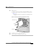
b. Pull the card out of the slot (Figure 7-50b) and place it directly into an
antistatic bag or other ESD-preventive container.
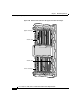
Figure 7-50 Removing an Alarm Card from the Upper Card Cage
Step 3 Replace the card by reversing the procedures in Steps 1 and 2.
28347
A
C
T
I
V
E
0
C
A
R
R
I
E
R
R
X
P
K
T
A
C
T
I
V
E
1
C
A
R
R
I
E
R
R
X
P
K
T
A
C
T
I
V
E
2
C
A
R
R
I
E
R
R
X
P
K
T
A
C
T
I
V
E
3
C
A
R
R
I
E
R
R
X
P
K
T
Q OC-3/STM-POS
6DS3–SMB P
/
H
/
F
DOWN
LOOP RA LA
CDHNT CD
TX
0
RX
TX
1
RX
TX
2
RX
TX
3
RX
TX
4
RX
TX
5
RX
12DS3–SMB P
/
H
/
F
DOWN
LOOP RA LA
CDHNT CD
TX
0
RX
TX
1
RX
TX
2
RX
TX
3
RX
TX
4
RX
TX
5
RX
TX
6
RX
TX
7
RX
TX
8
RX
TX
9
RX
TX
10
RX
TX
11
RX
A
C
TIV
E
C
A
R
R
IE
R
R
X
P
K
T
OC-48/STM-16-SCPOS
A
C
T
IV
E
0
C
A
R
R
I
E
R
R
X
C
E
L
L
OC-12/STM-4 ATM
FAST ETERNET
SLOT-0
ROUTE PROCESSOR
SLOT-1
COLL
LINK
TX
RX
RJ-45
MII
RESET
A
U
X
CONSOLE
EJECT
ALARM
ENABLED
FAIL
ACO/LT
ALARM
CSC
0
FAIL
1
0
1
2
ENABLED
CRITICAL
MAJOR
MINOR
SFC
Loosen
captive
screws
Use handle to pull
card out of slot
a
b