
Bridge/Router Installation and Configuration Guide

Chapter 7 Maintaining the Router
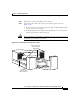
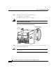
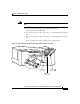
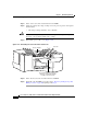
Removing and Replacing the DC-Input Power Shelf
7-78
Cisco 12016, Cisco 12416, and Cisco 12816 Router Installation and Configuration Guide
OL-11495-01
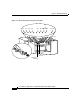
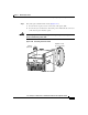
Step 4 Check the power supply status indicators:
• PWR OK (green)—Indicates that the PEM is operating normally, and the
source DC voltage is within the nominal operating range of –48 to –60
VDC.
When the PEM circuit breaker is switched on, this indicator lights.
• FAULT (yellow)—Indicates that the system detected a fault within the PEM
or the incoming voltage is too low. During normal operation, this indicator
remains off.
If the indicator is on:
–
Check that the source voltage is within the correct range: –40 to –72
VDC.
–
Toggle the PEM circuit breaker off and then on. If the indicator remains
on after several attempts to power it on, replace the existing PEM with a
spare.
–
If the spare PEM also fails, the problem could be a faulty power shelf
backplane connector. Power off the router and contact a Cisco service
representative for assistance.
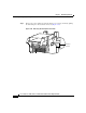
• TEMP (yellow)—Indicates that the PEM is in an overtemperature condition,
causing a shut-down to occur.
Note If the temp indicator is on, the fault indicator is also on.
–
Verify that the power supply fan is operating properly.
–
Verify that the blower modules are operating properly.
–
If the blower module is operating properly, replace the existing PEM with
a spare.
• TEMP (flashing yellow—2400 W PEM only)—Indicates that a power supply
fan is locked or malfunctioning.
Note If the temp indicator is flashing, the fault indicator is also on.
–
Check to see if the fan is operating. Remove any obstructions to the fan.
–
If the fan does not operate, replace the power supply.