
Bridge/Router Installation and Configuration Guide

7-57
Cisco 12016, Cisco 12416, and Cisco 12816 Router Installation and Configuration Guide
OL-11495-01
Chapter 7 Maintaining the Router
Removing and Replacing the Optional 2-Level AC-Input Power Shelf
Troubleshooting the AC Power Shelf Installation
Use the following procedure to troubleshoot the AC power shelf if it does not
operate properly after installation.
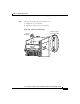
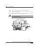
Step 1 Make sure that the power shelf is seated properly:
• The jackscrew is tightened securely.
• The captive screws on the flanges are tightened securely.
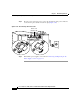
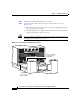
Step 2 Make sure each power supply is seated properly:
• The ejector lever is locked into place by its spring clip.
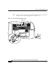
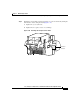
Step 3 Make sure the router is powered on and that all power cords are connected
properly:
• Power cords on the back panel of the power shelf are secured in place with
their retention clips.
• Power cords at the power source end are securely plugged into its own AC
power outlet.
• Make sure the source AC circuit breaker is switched on.
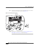
Step 4 Check the power supply status indicators:
• PWR OK (green)—Indicates that the power supply is operating normally, and
the source AC voltage is within the nominal operating range of 200
VA C t o
240
VAC. When the power supply is properly seated, this indicator is on.
• FAULT (yellow)—Indicates that the system has detected a fault within the
power supply or the incoming voltage is too low. During normal operation,
this indicator remains off.
If the indicator is on:
–
Check that the source voltage is within the correct range: 170 to 262 VAC
–
Remove and then apply power to the power supply by disconnecting its
power cord. If the indicator remains on, replace the existing power supply
with a spare.
–
If the spare power supply also fails, the problem could be a faulty power
shelf backplane connector. Power off the router and contact a Cisco
service representative for assistance.