
Bridge/Router Installation and Configuration Guide

Chapter 7 Maintaining the Router
Removing and Replacing the Standard AC-Input Power Shelf
7-46
Cisco 12016, Cisco 12416, and Cisco 12816 Router Installation and Configuration Guide
OL-11495-01
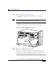
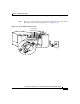
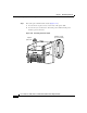
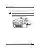
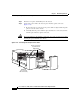
Step 3 Unseat the power shelf from the chassis (Figure 7-26):
a. Loosen the two captive screws on each side of the power shelf.
b. Loosen the ejector jackscrew to unseat the power shelf from the power
interface panel connectors.
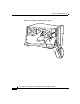
Figure 7-26 Unseating the Power Shelf
A
C
T
I
V
E
0
C
A
R
R
I
E
R
R
X
P
K
T
1
DOWN
LOOP RA LA
CDHNT CD
TX
0
RX
TX
1
RX
TX
2
RX
TX
DOWN
LOOP RA LA
CDHNT CD
TX
0
RX
TX
1
RX
TX
2
RX
TX
S
L
O
T
-
0
S
L
O
T
-
1
R
E
S
E
T
A
U
X
E
J
E
C
T
28020
Captive screws
(2 on each side)
Ejector
j
ackscrew