
Bridge/Router Installation and Configuration Guide

7-41
Cisco 12016, Cisco 12416, and Cisco 12816 Router Installation and Configuration Guide
OL-11495-01
Chapter 7 Maintaining the Router
Removing and Replacing an AC Power Supply
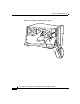
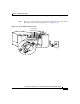
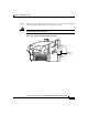
Step 8 Install the 2500 W power supply (Figure 7-24):
a. Slide the power supply into the bay until it mates with its backplane
connector.
Caution To prevent damage to the power shelf backplane connector, do not use excessive
force when inserting the power supply into its power shelf bay.
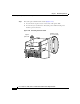
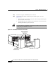
b. Lift up the ejector handle to hook it over the bottom edge of the power shelf.
c. Tighten the captive screw to secure the power supply in the shelf.
Figure 7-24 Installing a 2500 W AC Power Supply
Step 9 Plug the power supply cable into its AC outlet.
Step 10 Power on the circuit breaker to that AC outlet.
After the power-on sequence completes, the (green) PWR OK indicator on the
front of the power supply should light. If the indicator does not light, see the
“Troubleshooting the AC Power Supply Installation” section on page 7-42.
Pwr O
k
Fault
Te m
p
O
C
P
w
r O
k
Fault
Temp
O
C
129496
Pwr Ok
Fault
Te m
p
O
C