
Bridge/Router Installation and Configuration Guide

Chapter 5 Troubleshooting the Installation
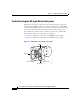
Troubleshooting the Power Subsystem
5-8
Cisco 12016, Cisco 12416, and Cisco 12816 Router Installation and Configuration Guide
OL-11495-01
Step 2 Make sure the router is powered on and that all power cords are connected
properly:
• Power cords on the back panel of the power shelf are secured in place with
their retention clips.
• Power cords at the power source end are securely plugged into their own
AC
power outlet.
• The source AC circuit breaker is switched on.
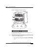
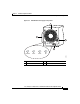
Step 3 Check the power supply status LED indicators:
• PWR OK (green)—Indicates the power supply is operating normally, and the
source AC voltage is within the nominal operating range of 200
VA C t o
240
VAC. This indicator lights when the power supply is properly seated in
position.
• FAULT (yellow)—Indicates the system detected a fault within the power
supply or the incoming voltage is too low. This indicator remains off during
normal operation.
If the indicator is on:
–
Check that the source voltage is within the correct range: 170 to 262 VAC
–
Remove and then apply power to the power supply by disconnecting its
power cord. If the indicator remains on, replace the existing power supply
with a spare.
–
If the spare power supply also fails, the problem could be a faulty power
shelf backplane connector. Power off the router and contact a Cisco
service representative for assistance.
• TEMP (yellow)—Indicates that the power supply is in an overtemperature
condition, causing a shut-down to occur.
Note If the temp indicator is on, the fault indicator is also on.
–
Verify that the power supply fan is operating properly.
–
Verify that the blower modules are operating properly.
–
If the power supply fan and blower modules are operating properly,
replace the existing power supply with a spare.