C H A P T E R 3 Channelized T3 Trunk Card The Cisco AS5800 universal access server supports a channelized T3 (CT3) ingress interface that provides asynchronous aggregation of channelized interfaces and multiplexing on a single T3 facility. The CT3 trunk card is installed in the Cisco 5814 dial shelf chassis in slots 0 to slot 5. The Cisco AS5800 currently supports as many as two CT3 trunk cards.
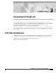
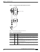
Chapter 3 Channelized T3 Trunk Card CT3 Trunk Card Overview CT3 Trunk Card FC PU FC PU PW R M AIN T PW R M AI NT Figure 3-1 HCPU R OO ALM P S F AI OO T RF LOS 3EN FE FE OO F AIS T RF LOS 3EN T3 LO OP T3 LO OP NL LA LM M ON IT OR # NL RA OO LM P LA LM M ON IT OR # HCPU RC VR Receive BNC connector UT (O TX ) (IN CHANNELIZED T3 12125 RX Transmit DSx1 connector Receive DSx1 connector ) XM TR Transmit BNC connector Each CT3 trunk card performs the following funct
Chapter 3 Channelized T3 Trunk Card CT3 Trunk Card Overview • Processes counting information for performance monitoring. • Supports online insertion and removal (OIR), a feature that allows you to remove and replace a trunk card in the Cisco 5814 dial shelf while the system is operating without disrupting other cards and their associated calls. If you remove a trunk card while the system is operating, all calls associated with the CT3 lines on that card are dropped.
Chapter 3 Channelized T3 Trunk Card CT3 Trunk Card Overview Clocking All Cisco AS5800 access server trunk cards use the same transmit clock. This clock can originate from the following sources: • TDM clock source—A priority value from 1 to 50 that is applied to a clock source when multiple clock sources are used • External clock source—A clock source external to the access server Clocks are prioritized by slot number (slots 0 to 5).
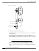
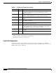
Chapter 3 Channelized T3 Trunk Card CT3 Trunk Card Overview CT3 Trunk Card Front Panel LED and Alphanumeric Indicators FC PU FC PU PW R M AIN T PW R M AI NT Figure 3-3 HCPU HCPU CHANNELIZED T3 OO F AI S T RF LOS 3EN 12240 RX (IN ) TX (O UT ) XM TR RC VR FE FE OO F AIS T RF LOS 3EN T3 LO OP T3 LO OP NL LA LM R OO ALM P M ON IT OR # NL RA OO LM P LA LM M ON IT OR # Alphanumeric display Table 3-1 lists the CT3 trunk card LEDs and their functions.
Chapter 3 Channelized T3 Trunk Card CT3 Trunk Card Overview Table 3-1 CT3 Trunk Card LED Indicators (continued) LED Color Description RALM Yellow Remote alarm—Lights to indicate a T1 alarm condition was encountered by software for a particular port; remains OFF when the operating condition is normal. NLOOP Yellow Network loop—Lights to indicate that at least one T1 is unavailable (status indicator); remains OFF when the operating condition is normal.
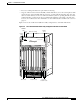
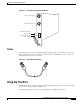
Chapter 3 Channelized T3 Trunk Card Using the Test Port Figure 3-4 CT3 Trunk Card Front Panel Connectors RC VR Receive BNC connector (O TX ) (IN CHANNELIZED T3 12241 Receive DSx1 bantam jack connector RX Transmit DSx1 bantam jack connector UT ) XM TR Transmit BNC connector Cables The CT3 trunk card receives and transmits 45 Mbps signals through a 75-ohm cable, using common BNC coaxial cable connectors (see Figure 3-5).
Chapter 3 Channelized T3 Trunk Card Using the Test Port Trunk Card Bantam Jacks The test port is a set of bantam jack connectors located at the bottom of the CT3 front panel (see Figure 3-4). The bantam jacks allow the connection of an external test device (for example, a FIREBERD test device) to test any of the 28 individual T1 circuits in drop-and-insert mode or to monitor an individual T1 circuit in monitor mode. • In drop-and-insert mode, the T1 line is dropped out of service.
Chapter 3 Channelized T3 Trunk Card Using the Test Port Monitor Mode To monitor a particular T1 line at the test port, follow these steps: Step 1 Verify that drop-and-insert mode is disabled on the CT3 controller by entering the show command, as follows: AS5800# sh controller t3 shelf/slot/unit The following is sample output from the sh controller t3 command if drop-and-insert mode is disabled: AS5800# show controller t3 1/1/0 T3 1/1/0 is up. Applique type is Channelized T3 No alarms detected.
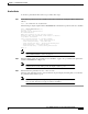
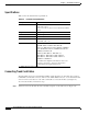
Chapter 3 Channelized T3 Trunk Card Using the Test Port Specifications Table 3-2 lists the CT3 trunk card specifications. Table 3-2 CT3 Trunk Card Specifications Description Specification Dimensions H x W x L 15.4 x 0.08 x 18.7 in. (39.12 x 0.203 x 47.5 cm) without the carrier 15.5 x 1.23 x 19 in. (39.37 x 3.12 x 48.26 cm) with the carrier Weight 8 lb (3.6 kg) Transmission bit rate 44,736 Mbps MTBF 1 Exceeds 50,000 hr Power requirements +3.3 VDC, 8A, 5% +5.
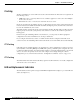
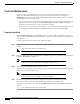
Chapter 3 Channelized T3 Trunk Card Using the Test Port Figure 3-6 CT3 Trunk Card BNC Cable Connections RC VR Receive BNC connector (O TX ) (IN CHANNELIZED T3 Step 2 12241 Receive DSx1 bantam jack connector RX Transmit DSx1 bantam jack connector UT ) XM TR Transmit BNC connector Attach the network end of your CT3 cable to your external network. Configuring Cable Length When you configure your CT3 trunk cards, you must include the length of the cable connected to the card.
Chapter 3 Channelized T3 Trunk Card Configuring the CT3 Trunk Card To complete the hardware installation, verify that the trunk card LEDs operate properly by observing the following LED states: • The power LED is ON. If the power LED remains OFF, verify that the card is seated properly. If the power LED lights on other trunk cards in the dial shelf, try inserting the trunk card in a different slot.
Chapter 3 Channelized T3 Trunk Card Configuring the CT3 Trunk Card Table 3-3 Step 1 T3 Configuration Commands Command Description AS5800> enable Password: password AS5800# Enter the enable command. Enter your password. You are in privileged EXEC mode when the prompt changes to AS5800#. Step 2 AS5800# configure terminal Enter configuration commands, one per line. End with CNTL/Z. AS5800(config)# Enter global configuration mode by entering the configure terminal command.
Chapter 3 Channelized T3 Trunk Card Configuring the CT3 Trunk Card Table 3-3 Step 13 T3 Configuration Commands (continued) Command Description AS5800(config)# dial-tdm-clock priority {1-50} {external | trunk-slot} {0-5} ds3-port 0 port {1-28} Configure clock priority, which is a value from 1 to 50. Select a clocking source by selecting an external reference clock or a trunk card. If you are using an external reference clock, no other CLI is needed.
Chapter 3 Channelized T3 Trunk Card Configuring the CT3 Trunk Card AS5800# show controller t3 T3 1/0/0 is up. Applique type is Channelized T3 No alarms detected. FEAC code received: No code is being received Framing is M23, Line Code is B3ZS, Clock Source is Line.
Chapter 3 Channelized T3 Trunk Card Configuring the CT3 Trunk Card A typical T3 controller configuration in a running-configuration file appears as follows: T3 controller configuration: ---------------------------controller T3 1/0/0 framing m23 clock source line cablelength 224 t1 1 controller t1 2 controller t1 3 controller t1 4 controller t1 5 controller t1 6 controller t1 7 controller t1 8 controller t1 9 controller t1 10 controller t1 11 controller t1 12 controller t1 13 controller t1 14 controller t