Getting Started Guide Getting Started Guide for the Catalyst Express 500 Switches INCLUDING LICENSE AND WARRANTY 1X 2 1 4 3 5 6 7 8 9 10 11 12 11X 13X 12X 14X 13 14 15 16 17 18 19 2X POWE 20 21 22 23 R OVER ETHE RNET 24 23X Cataly 24X st Exp res s 500 25 25 26 SYSTEM ALERT PoE 26 SETUP SERIES
About this guide This guide explains how to configure a Catalyst Express 500 switch for the first time. Basic configuration involves assigning network settings and a password to the switch. After you complete the basic configuration, you can access the internal device manager application to manage and customize the switch. The device manager is an easy-to-use interface that provides tools for configuring, monitoring, and problem solving.
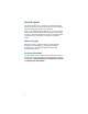
Quick tour This illustration shows the Ethernet ports, LEDs, and other features on the switch. To set up the switch, you use the SETUP button, an Ethernet port, and the SYSTEM, SETUP, and port LEDs. The model shown is a Catalyst Express 500-24LC. Your switch model might look slightly different.
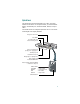
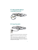
1 Unpack the box Verify that you have received the items shown here. If any item is missing or damaged, contact your Cisco representative or reseller for instructions.
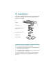
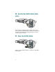
2 Make sure that nothing is connected to the switch 1X 2 1 4 3 5 6 7 8 9 10 11 12 11X 13X 12X 14X 13 14 15 16 17 18 19 2X POWE 20 21 22 23 R OVER ETHER NET 24 23X Catalyst 24X Express 500 SERIES 25 25 26 26 SYSTEM ALERT PoE RPS SETUP 3 Power the switch Connect the AC power cord to the connector on the switch rear panel. Next, connect the power cord plug to a grounded AC outlet.
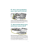
4 Wait for the SETUP LED to blink green oE 4 1X 2 1 4 3 5 6 7 8 9 10 11 12 11X 13X 12X 14X 13 14 15 16 17 18 19 20 2X POWE 21 22 23 R OVER ETHER 24 NET 23X Cisco 24X 2960 series +PoE-4 25 25 SYSTEM ALERT PoE RPS 26 26 SETUP SYSTEM ALERT PoE SETUP When POST has completed and the SYSTEM LED is solid green, the SETUP LED blinks green. The switch is ready to be configured. (If the SETUP LED stops blinking, you can still continue with the next step.
6 When a switch port LED blinks green, connect your PC to that port 1X 2 1 4 3 5 6 7 8 9 10 11 12 1 2X POWER OVER 11X 13X 12X 14X 13 14 2 15 16 17 18 19 20 21 1X ETHER NET 22 23 24 3 23X 4 24X Catalyst Express 500 SERIES 25 25 SYSTEM ALERT PoE RPS 26 26 SETUP 2X POWE R ETHER OVER NET Connect one end of the Ethernet cable to the Ethernet port on your PC. Connect the other end to the switch port with the blinking LED.
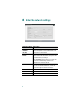
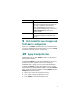
Enter the network settings Network Settings Description Management Interface (VLAN) We recommend using the default, VLAN 1. The management VLAN establishes an IP connection to the switch. IP Assignment Mode We recommend using the default, Static, which means that the switch always has the IP address that you assign. Use the DHCP setting when you want the switch to automatically obtain an IP address from a DHCP server. IP Address Enter the IP address for the switch.
Network Settings Description Password Enter a password. The password can be from 1 to 25 alphanumeric characters, can start with a number, is case sensitive, allows embedded spaces, but does not allow spaces at the beginning or end. In the Confirm Password field, enter your password again. Optional Settings Enter a Host Name for the switch. The date and time fields are populated from your PC.
We recommend that you apply the Cisco Smartports roles now. The ports are then correctly configured before they are connected to devices. Smartports roles provide optimal performance on port connections, including appropriate levels of reliability, security, and availability. They also help prevent many problems caused by port misconfigurations. The only requirements are to decide and write down which switch port will be connected to which device type. You can connect a WAN device to any port.
Smartports Roles Description Access Point Apply this role on switch ports connecting to wireless access points (APs). Connected to the AP are mobile devices, such as wireless laptop PCs. Printer Apply this role on switch ports connecting to a printer, such as a network printer or an external print server. Guest Apply this role on switch ports that are used by guests and visitors. Guests have access to the Internet but not access to your internal network.
11 Install the switch Before you install the switch, review the Regulatory Compliance and Safety Information document that came with your switch. For more information about installation, see the User Guide for the Catalyst Express 500 Switches online at Cisco.com. When selecting an installation site, observe these guidelines: • Cabling is away from sources of electrical noise, such as radios, power lines, and fluorescent lighting fixtures.
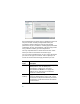
1X 2 1 4 3 5 6 7 8 9 10 11 12 11X 13X 12X 14X 13 14 15 16 17 18 19 20 2X POWE 21 22 23 R OVER ETHER NET 24 23X Catalyst Express 500 SERIE S 25 24X 25 26 26 SYSTEM ALERT PoE RPS SETUP Insert the switch into the 19-inch rack and align the bracket in the rack. Use either the 10-32 pan-head screws, or the 12-24 pan-slotted screws to secure the switch in the rack. Use the black Phillips screw to attach the cable guide to either bracket.
25 2960 +PoE-4 OV 6 7 ETHER NET 14X 12X 26 26 25 25 Cisco 2960 23X 1X 1 2 2X POWER OVER 3 4 ETHERNET 5 6 7 8 9 10 11 12 11X 13X 13 14 15 16 17 18 19 20 21 22 23 24 24X series +PoE-4 1X 1 2 3 2X 4 POWE R 5 ER 8 9 10 11 12 X 11 X 13 13 14 X 12 15 X 14 16 17 18 19 20 21 22 23 24 X 23 X 24 25 Cisco s e ri e s 26 26 Wall-mounting Position the mounting bracket and screw on the side of the switch, rotated 90-degrees from the vie
12 Connect devices 1X 2 1 4 3 5 6 7 8 9 10 11 12 11X 13X 13 14 15 16 17 8 2X POWE 19 18 19 20 20 21 21 R OVER ETHER NET 14X 22 23 22 23 12X 24 24 23X Catalyst 23X Cataly 25 24X 25 Express 26 26 24X 25 500 st Exp ress 500 25 SYSTEM ALERT PoE RPS SERIES SERI SETUP 26 26 SYSTEM ALERT PoE RPS SETUP When you connect devices to the switch ports, refer to the Smartports role assignments that you recorded in Step 10.
• The dual-purpose uplink ports establish a link through either the SFP module port or the 10/100/1000BASE-T port, but not both at the same time. An SFP module port has precedence over a 10/100/1000BASE-T port. If an SFP module port has a link, that link is active. If the SFP port does not have a link and the 10/100/1000BASE-T port does, that link is active. Reselection occurs when the active link is disconnected. For a list of supported modules, see the Catalyst Express 500 Switch Release Notes on Cisco.
The simplest way to configure, manage, and monitor the switch is by using the device manager. You can access the device manager from anywhere in your network through a web browser. Follow these steps: 1. Set up and install the switch in your network, and connect devices as described in this guide. 2. Launch a web browser on your PC. 3. Enter the switch IP address (the address that you assigned in Step 8) in the web browser, and press Enter. The device manager page appears. 4.
Checklist Recommendation Did you start a browser session on your PC before the SETUP LED was solid green? If yes, or you are not sure, restart the switch. Perform Step 2 through Step 6. When the SETUP LED is solid green, start a browser session on your PC. Complete the set-up procedure. Did you start a browser session on your PC and the set-up page did not appear? If the window does not appear, enter a URL in your browser, such as cisco.com, or another well-known website.
Cisco Limited Lifetime Hardware Warranty Terms There are special terms applicable to your hardware warranty and various services that you can use during the warranty period. Your formal Warranty Statement, including the warranties and license agreements applicable to Cisco software, is available on Cisco.com. Follow these steps to access and download the Cisco Information Packet and your warranty and license agreements from Cisco.com. 1. Launch your browser, and go to this URL: http://www.cisco.
3. To read translated and localized warranty information about your product, follow these steps: a. Enter this part number in the Warranty Document Number field: 78-6310-02C0 b. Select the language in which you would like to view the document. c. Click Go. The Cisco warranty page appears. d. Read the document online, or click the PDF icon to download and print the document in Adobe Portable Document Format (PDF). You can also contact the Cisco service and support website for assistance: http://www.cisco.
To Receive a Return Materials Authorization (RMA) Number Contact the company from whom you purchased the product. If you purchased the product directly from Cisco, contact your Cisco Sales and Service Representative. Complete the information below, and keep it for reference.
Corporate Headquarters Cisco Systems, Inc. 170 West Tasman Drive San Jose, CA 95134-1706 USA www.cisco.com Tel: 408 526-4000 800 553-NETS (6387) Fax: 408 526-4100 European Headquarters Cisco Systems International BV Haarlerbergpark Haarlerbergweg 13-19 1101 CH Amsterdam The Netherlands www-europe.cisco.com Tel: 31 0 20 357 1000 Fax: 31 0 20 357 1100 Americas Headquarters Cisco Systems, Inc. 170 West Tasman Drive San Jose, CA 95134-1706 USA www.cisco.