
Network Card User Manual

42
Catalyst 6500 Series DFC3A, DFC3B, and DFC3BXL Installation Note
78-15893-06
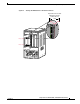
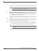
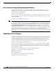
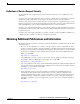
Attaching Your ESD Grounding Strap
Figure 29 Attaching the ESD Wrist Strap Clip to the System Ground Lug Screw
In addition, follow these guidelines when handling modules:
• Handle carriers by available handles or edges only; avoid touching the printed circuit boards or
connectors.
• Place a removed component board-side-up on an antistatic surface or in a static shielding container.
If you plan to return the component to the factory, immediately place it in a static shielding
container.
• Never attempt to remove the printed circuit board from the metal carrier.
Caution For safety, periodically check the resistance value of the antistatic strap. The measurement should be
between 1 and 10 megohm (Mohm).
S
U
P
E
R
V
IS
O
R
2
W
S
-X
6K
-S
U
P
2
-2
G
E
S
T
A
T
U
S
S
Y
S
T
E
M
C
O
N
S
O
L
E
P
W
R
M
G
M
T
R
E
S
E
T
C
O
N
SO
LE
C
O
N
SO
LE
P
O
RT
M
O
D
E
P
CM
C
IA E
JE
CT
P
O
R
T 1
P
O
RT
2
S
witch Load
100%
1%
L
IN
K
L
IN
K
O
S
M
-4
O
C
1
2
P
O
S
-S
I
4
P
O
R
T
O
C
-1
2
P
O
S
S
M
IR
S
T
A
T
U
S
1
1
2
2
3
3
4
4
R
E
S
E
T
L
I
N
K
L
I
N
K
L
IN
K
L
I
N
K
C
A
R
R
I
E
R
A
L
A
R
M
C
A
R
R
I
E
R
A
L
A
R
M
C
A
R
R
I
E
R
A
L
A
R
M
C
A
R
R
I
E
R
A
L
A
R
M
A
C
T
I
V
E
T
X
R
X
T
X
P
O
R
T
1
R
X
A
C
T
I
V
E
T
X
R
X
T
X
P
O
R
T
2
R
X
A
C
T
IV
E
T
X
R
X
T
X
P
O
R
T
3
R
X
A
C
T
IV
E
T
X
R
X
T
X
P
O
R
T
4
R
X
O
S
M
-
4
O
C
1
2
P
O
S
-S
I
4
P
O
R
T
O
C
-1
2
P
O
S
S
M
IR
S
T
A
T
U
S
1
1
2
2
3
3
4
4
R
E
S
E
T
L
I
N
K
L
I
N
K
L
I
N
K
L
I
N
K
C
A
R
R
I
E
R
A
L
A
R
M
C
A
R
R
I
E
R
A
L
A
R
M
C
A
R
R
I
E
R
A
L
A
R
M
C
A
R
R
I
E
R
A
L
A
R
M
A
C
T
I
V
E
T
X
R
X
T
X
P
O
R
T
1
R
X
A
C
T
I
V
E
T
X
R
X
T
X
P
O
R
T
2
R
X
A
C
T
I
V
E
T
X
R
X
T
X
P
O
R
T
3
R
X
A
C
T
I
V
E
T
X
R
X
T
X
P
O
R
T
4
R
X
144607
System ground
connector
Grounding lug
Side view of
grounding lug
ESD ground
strap
Slide clip
behind screw
Clip installed
behind screw
Clip
Screw