
Network Card User Manual

33
Catalyst 6500 Series DFC3A, DFC3B, and DFC3BXL Installation Note
78-15893-06
Removing and Installing Modules in the Chassis
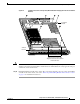
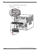
Step 5 Depending on the orientation of the slots in the chassis (horizontal or vertical), perform one of the
following two sets of substeps:
Horizontal slots
a. Place your thumbs on the left and right ejector levers, and simultaneously rotate the levers outward
to unseat the module from the backplane connector.
b. Grasp the front edge of the module and slide the module part of the way out of the slot. Place your
other hand under the module to support the weight of the module. Do not touch the module circuitry.
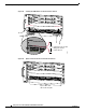
Vertical slots
a. Place your thumbs on the ejector levers located at the top and bottom of the module, and
simultaneously rotate the levers outward to unseat the module from the backplane connector.
b. Grasp the edges of the module, and slide the module straight out of the slot. Do not touch the module
circuitry.
Step 6 Place the module on an antistatic mat or antistatic foam.
Installing a Module in the Chassis
Caution To prevent ESD damage, handle modules by the carrier edges only and wear grounding wrist straps.
Warning
Invisible laser radiation may be emitted from disconnected fibers or connectors. Do not stare into
beams or view directly with optical instruments.
Statement 1051
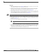
To install a module in the chassis, perform these steps:
Step 1 Attach an ESD grounding strap to your wrist and to ground. (If you are unsure about the correct way to
attach an ESD grounding strap, refer to the “Attaching Your ESD Grounding Strap” section on page 40
for instructions.)
Step 2 Verify that the captive installation screws are tightened on all modules installed in the chassis. This
assures that the EMI gaskets on all modules are fully compressed in order to maximize the opening space
for the new module or the replacement module.
Note If the captive installation screws are loose, the EMI gaskets on the installed modules will push
adjacent modules toward the open slot, reducing the opening size and making it difficult to
reinstall the module.
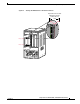
Step 3 Fully open both ejector levers on the module. (See Figure 23.)