
Network Card User Manual

13
Catalyst 6500 Series DFC3A, DFC3B, and DFC3BXL Installation Note
78-15893-06
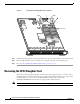
Removing the DFC3 Daughter Card
Removing the DFC3 Daughter Card from Modules Without Stiffener Brackets
To remove the DFC3 daughter card from modules that are not equipped with a stiffener bracket, follow
these steps:
Warning
During this procedure, wear grounding wrist straps to avoid ESD damage to the card. Do not directly
touch the backplane with your hand or any metal tool, or you could shock yourself.
Statement 94
Step 1 Attach an ESD grounding strap to your wrist and to ground. (If you are unsure about the correct way to
attach an ESD grounding strap, refer tothe “Attaching Your ESD Grounding Strap” section on page 40
for instructions.)
Step 2 Remove the Ethernet module from the Catalyst 6500 series switch. (If you are unsure about the correct
procedure for removing a module from the switch chassis, refer to the “Removing and Installing
Modules in the Chassis” section on page 32 for removal instructions.)
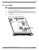
Step 3 Place the Ethernet module on an antistatic mat with the front of the module facing toward you.
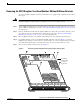
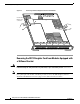
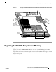
Step 4 If your DFC daughter card has a small metal installation bracket as shown in Figure 3, use a No.1
Phillips-head screwdriver to remove the two cap nuts and the one screw securing the bracket. Set them
aside with the bracket. If there is no bracket, just remove the two cap nuts and the one screw.
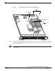
Step 5 Remove the remaining securing screws. (See Figure 3.)
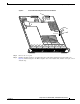
Figure 3 Removing the DFC Daughter Card Securing Screws and Cap Nuts
WS-X5530
154456
S
T
A
T
U
S
W
S
-X
6724-S
F
P
24P
O
R
T
G
IG
A
B
IT
E
T
H
E
R
N
E
T - S
FP
1
2
3
4
5
6
7
8
9
10
1
1
12
13
1
4
15
1
6
7
1
18
19
20
2
1
2
2
23
24
Installation
bracket. May
or may not
be present.