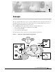
C H A P T E R Concepts The Cisco Catalyst 8500 router is a Layer 3–enhanced ATM switch that seamlessly integrates Layer 3 and ATM switching into a single chassis. Additionally, the Cisco Catalyst 8500 switch provides an integrated ATM and Gigabit Ethernet network solution.
Chapter 1 The Concepts chapter describes EM concepts and covers the following information: • EM Documentation Set • Cisco EMF Software Features • EM Software Features • EM Objects and Interfaces • Views • Object States Cisco Catalyst 8500 Manager User Guide 1-2 Concepts
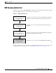
Chapter 1 Concepts EM Documentation Set EM Documentation Set This guide is one part of the C8500MGR EM documentation set. The following figure displays all of the guides in the EM documentation set and details the contents of each. Figure 1-2 EM Documentation Set Cisco Element Management Framework Installation and Administration Guide (Version 3.
Chapter 1 Concepts Cisco EMF Software Features Cisco EMF Software Features Cisco EMF provides a flexible framework which supports a variety of EM applications, making it possible to manage multiple device types within a given network on a single system. Common network management functionality provides for complete management of the logical and physical components of the network.
Chapter 1 Concepts EM Software Features EM Software Features Installed with Cisco EMF, the EM allows for precise management of the device(s) it supports through custom GUI windows and modeling behavior. Invoked from the Cisco EMF Map Viewer application, the EM provides Fault, Configuration, Accounting, Performance, and Security (FCAPS) windows on chassis, module, interface, and connection levels as applicable.
Chapter 1 Concepts EM Objects and Interfaces EM Objects and Interfaces The EM manages both physical and logical objects as follows: • Physical—Represents tangible components and devices such as the chassis (hardware frame), module interfaces and port adapters, and interfaces • Logical—Represents intangible, more abstract features, such as ATM connections objects and profiles Fault, Configuration, Accounting, Performance, and Security (FCAPS) windows are accessible on both physical and logical EM obje
Chapter 1 Concepts EM Objects and Interfaces Table 1-1 Physical Objects and Management Functions (continued) Physical Object Management Functions Physical Interfaces—Each module (interface or port adapter) has at least one, if not multiple, physical interfaces (ports). The type of physical interface is equivalent to the type of module the interface resides on.
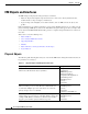
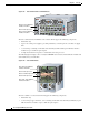
Chapter 1 Concepts EM Objects and Interfaces Figure 1-3 Cisco 8510 and Cisco LS1010 Chassis Slots 0-1: Port adapters/ Interface modules 100Mbps Tx 100Mbps Tx LINK Rx 100 Base Fx FAST ETHERNET MODULE LINK Rx 1 S 1 2 100Mbps Tx TU AT ST RE SE 100Mbps Tx LINK Rx 2 100Mbps Tx AT 100Mbps Tx LINK Rx 100Mbps Tx LINK Rx 1 US LINK Rx 100Mbps Tx LINK Rx 5 100Mbps Tx 100Mbps Tx LINK Rx 6 LINK Rx 100Mbps Tx 100Mbps Tx LINK Rx 7 LINK Rx 100Mbps Tx LINK Rx 8 LINK Rx 100Mb
Chapter 1 Concepts EM Objects and Interfaces Caution • Up to 2 route processor modules, where 1 processor is the primary and 1 is redundant • Up to 3 switch processor modules (Switch Fabric Cards), where 2 processors are primary and 1 is redundant • Up to 2 AC or DC power supplies, providing redundancy in the event that one supply fails Do not mix power supplies within the Cisco Catalyst 8540.
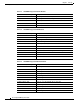
Chapter 1 Concepts EM Objects and Interfaces Table 1-3 C8500MGR Supported Generic Modules Module Interface/Port Adapter Description C85MS–4E1–FRRJ48 C8500 4–port E1 Frame–Relay PAM C85MS–SCAM–2P C8540 SuperCAM for Port Adapter Modules (PAMs) WAI–E1C–4BNC 4 Port E1 (circuit emulation) BNC PAM WAI–E1C–4RJ48 4 Port E1 (circuit emulation) RJ–48 PAM WAI–T1C–4RJ48 4 Port T1 (circuit emulation) RJ–48 PAM Table 1-4 C8500MGR Supported ATM Modules Module Interface/Port Adapter Description C8540–A
Chapter 1 Concepts EM Objects and Interfaces Physical Interfaces and Logical Interface Technologies Physical interfaces and logical interface technologies are modeled as objects below a parent module. As mentioned before, the type of module characterizes the type of interface. Interface types further break down into two categories, physical interfaces and logical interface technologies. Physical interfaces are the ports which exist on line cards.
Chapter 1 Concepts EM Objects and Interfaces Table 1-6 Physical Interfaces, Related Technologies and Windows Interface Type Physical and Logical Interface Technologies Ethernet Ethernet Configuration Status Performance Profile IP Configuration SONET Status Performance ATM Fault Configuration Status Performance Profile IP Configuration SONET FCAPS Service Windows Although not technology–specific, physical or logical, generic support is available through Configuration, Status, and Performa
Chapter 1 Concepts Views Views Views are accessible by clicking the Viewer icon on the Cisco EMF launchpad. These views appear in the frame at the left of the window when you open the Map Viewer window (see the following figure for an example). Views model hierarchical relationships between objects, both physical and logical. Objects are organized into different views and can exist in multiple views simultaneously by reference. Each object can have a number of parent and child objects.
Chapter 1 Concepts Views Component Managed View The Component Managed view displays all objects within the Cisco EMF system. For example, say you have two types of EM applications installed in Cisco EMF: EM A and EM B. Information for both the EM A and EM B display within the Component Managed view. Additionally, the Component Managed view also displays ATM connections such as PVCs and SPVCs. Connection objects are not visible in any other view.
Chapter 1 Concepts Views Layer 3 QoS View The Layer 3 QoS view displays only Layer 3 QoS objects within the EM, such as the following: • Access Lists • Committed Access Rate (CAR) objects • Weighted Random Early Detection (WRED) objects You can work within this view to create and configure Access Lists or CAR or WRED objects by accessing the respective EM menus. C8500MGR does not provide Layer 3 QoS support. Neither the Layer 3 QoS view nor the respective menus are applicable to the C8500MGR.
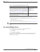
Chapter 1 Views Figure 1-7 Physical View Chassis Map Cisco Catalyst 8500 Manager User Guide 1-16 Concepts
Chapter 1 Concepts Object States Object States Object states reflect the life cycle of an object. Whatever stage the object is in at any given time displays in the state type. The state of an object can change frequently, depending upon what actions take place on the object. All objects within the EM are in a specific state which appears at the bottom left corner of each FCAPS window. The following figure highlights an object’s state.
Chapter 1 Concepts Object States Decommissioned State The decommissioned state indicates that an object is not managed. When you manually deploy an object, the object is normally put into the decommissioned state. Tip Initially deployed objects are decommissioned to leave you with the option of managing the object or not. If you want to manage the object, you must commission the object.
Chapter 1 Concepts Object States Lost Comms The lost comms (lost communications) state indicates that the object is not responding to heartbeat polling. The EM can apply this state to a chassis, module, or interface. When an object is in the lost comms state, heartbeat polling occurs on the object. When the object responds to heartbeat polling, it moves out of the lost comms state. For example, say an ATM module in the EM was predeployed.
Chapter 1 Concepts Object States the chassis enters the mismatched state. To rectify this problem, you must either delete the predeployed chassis and deploy the correct one, or fix the IP address by re–entering the correct one in the chassis Management Information window. Synchronizing The EM provides capabilities to synchronize hardware components and settings between the management system (EM) and the device. By default, the device is the master in the synchronization policy.