Catalyst 6000 Family Content Switching Module Installation and Configuration Note Product Number: WS-X6066-SLB-APC This publication contains the procedures for installing and configuring the Catalyst 6000 family Content Switching Module (CSM). This publication does not contain the instructions to install the Catalyst 6000 family switch chassis. For information on installing the switch chassis, refer to the Catalyst 6000 Family Installation Guide.
Overview • Regulatory Standards Compliance, page 54 • Translated Safety Warnings, page 54 • Related Documentation, page 58 • Obtaining Documentation, page 59 • Obtaining Technical Assistance, page 60 Overview The CSM provides high-performance connections between network devices and server farms (groups of real servers) based on Layer 4 through 7 packet information. Clients connect to the CSM by supplying the virtual IP address (VIP) of the virtual server.
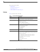
Overview These sections describe the CSM: • Features, page 3 • Front Panel Description, page 4 • Operation Mode, page 5 • Client-to-CSM-to-Server Traffic Flow, page 7 Features Table 1 describes the features of the CSM.
Overview Table 1 Content Switching Module Features (continued) Feature Description Health Monitoring TCP, HTTP, ICMP, Telnet, FTP Other Features SSL session ID, cookie and source IP address-based sticky connections Fragmented IP frames support MTU2 of 9000 Load and availability reporting supporting remote monitoring and management High availability preventing service disruptions Redundant modules configured for fault-tolerance support 1. SSL = Secure Socket Layer 2.
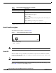
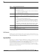
Overview Table 2 Content Switching Module Status LED Color Off Description • The module is waiting for the supervisor engine to grant power. • The module is not online. • The module is not receiving power, which could be caused by the following: – Power is not available to the CSM. – Module temperature is over the limit1. Red • The module is released from reset by the supervisor engine and is booting. • If the boot code fails to execute, the LED stays red after power up.
Overview When the client-side and server-side VLANs are on the same subnets, you can configure the CSM in single subnet (bridge) mode. For more information, see the “Single Subnet (Bridge) Mode Configuration” section on page 35. When the client- and server-side VLANs are on different subnets, you can configure the CSM to operate in a secure (router) mode. For more information, see the “Secure (Router) Mode Configuration” section on page 37.
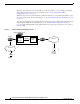
Overview Client-to-CSM-to-Server Traffic Flow This section describes how the traffic flows between the client and server in a CSM environment. (See Figure 3.) Figure 3 Client-to-Content Switching Module-to-Server Traffic Flow W 5 .com 6 4 VIP X 7 2 3 Z 47528 DNS server Y www.example.com web server farm Note The numbers in Figure 3 refer to the steps in the following procedure. When you enter a request for information by entering a URL, the traffic flow is as follows: Step 1 You enter a URL.
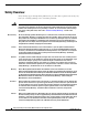
Safety Overview Safety Overview Safety warnings appear throughout this publication in procedures that, if performed incorrectly, may harm you. A warning symbol precedes each warning statement. Warning This warning symbol means danger. You are in a situation that could cause bodily injury. Before you work on any equipment, be aware of the hazards involved with electrical circuitry and be familiar with standard practices for preventing accidents.
System Requirements Aviso Este símbolo de aviso indica perigo. Encontra-se numa situação que lhe poderá causar danos físicos. Antes de começar a trabalhar com qualquer equipamento, familiarize-se com os perigos relacionados com circuitos eléctricos, e com quaisquer práticas comuns que possam prevenir possíveis acidentes. Para ver as traduções dos avisos que constam desta publicação, consulte a secção “Translated Safety Warnings” - “Traduções dos Avisos de Segurança” neste documento.
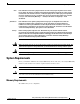
System Requirements Hardware Supported Before you can use the CSM, you must have a Supervisor Engine 1A with an MSFC and a Policy Feature Card (PFC), or a Supervisor Engine 2 with an MSFC, and any module with ports to connect server and client networks. The PFC is required for the VLAN access control list (VACL) capture functionality. Caution The WS-X6066-SLB-APC Content Switching Module is not fabric enabled.
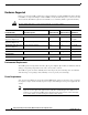
Required Tools Software Requirements Catalyst 6000 family CSM software release 1.1(1) requires Cisco IOS Release 12.1(6)E or 12.1(7)E. Catalyst 6000 family CSM software release 1.2(1) requires Cisco IOS Release 12.1(8a)E or later only. CSM Software Release Software Part Number Hardware Cisco IOS Release Added Features 1.1(1) SC6k-SLB-APC-1.1 Supervisor Engine 1A with MSFC and PFC 12.1(6)E or 12.1(7)E Initial Release 1.2(1) SC6K-1.2-CSM Supervisor Engine 1A with MSFC and PFC 12.
Installing the Content Switching Module • Catalyst 6000 family switch chassis • Servers that are connected to the Catalyst 6000 family switch through a bridged or a routed connection • Management station that is available through a Telnet or a console connection to perform configuration tasks Installing the CSM This section describes how to install the CSM into the Catalyst 6000 family switch.
Installing the Content Switching Module Figure 4 Slot Numbers on Catalyst 6000 Family Switches WS-X6K-SUP2-2GE Supervisor engine ST 1 AT US SY ST OL EM T E NS R CO M PW GM SE Switch 100% T Load CONSOLE PORT MODE RE PORT 1 PORT 2 CONSOLE SUPERVISOR2 PCMCIA EJECT 1% K LIN K LIN WS-X6K-SUP2-2GE Redundant supervisor engine 2 ST AT US SY ST OL EM T E NS CO R PW M GM SE Switch 100% T Load CONSOLE PORT MODE RE PORT 1 PORT 2 CONSOLE SUPERVISOR2 PCMCIA EJECT 1
Installing the Content Switching Module Step 4 Loosen the captive installation screws that secure the switching-module filler plate (or an existing switching module) to the desired slot. Step 5 Remove the switching-module filler plate (or an existing switching module). Step 6 Hold the handle of the CSM with one hand, and place your other hand under the carrier support. Do not touch the printed circuit boards or connector pins. Step 7 Place the CSM in the slot.
Verifying the Installation Figure 6 Ejector Levers and Captive Installation Screws WS-X6K-SUP1 ST AT U S SY ST EM AC TIV E PW R M G R M ES T ET CONSOLE Switch 100% Load PORT 1 PORT 2 CONSOLE LIN K MODE PCMCIA 1% LIN K PORT EJECT 16059 SUPERVISOR I Ejector lever Step 9 Caution Using the thumb and forefinger of each hand, simultaneously push in the left and right levers to fully seat the CSM in the backplane connector. Always use the ejector levers when installing or removing the CSM.
Upgrading to a New Software Release Using the Command-Line Interface The software interface for the CSM is the Cisco IOS interface. To understand the Cisco IOS command-line interface and Cisco IOS command modes, refer to Chapter 2 in the Catalyst 6000 Family IOS Software Configuration Guide. Note Because of each prompt’s character limit, some prompts may be truncated.
Upgrading to a New Software Release Caution You must enter the exit command to terminate sessions with the CSM being upgraded. If you do not terminate the session and you remove the CSM from the Catalyst 6000 family chassis, you cannot issue configuration commands to the CSM unless you press Ctrl + ^, enter x, and type the disconnect command at the prompt.
Upgrading to a New Software Release Upgrading from a PCMCIA Card Upgrade the CSM from a removable Flash (PCMCIA) card inserted in the supervisor engine as follows: Step 1 Enable the TFTP server to supply the image from the removable Flash card: Router> Router> enable Router# conf t Router(config)# tftp-server slotx:c6slb-apc.revision-num.bin where x = 0 if the PCMCIA card is installed in supervisor engine PCMCIA slot 0.
Configuring the Content Switching Module Step 6 Enter the show command as described in “Configuring VLANs” section on page 21 to verify the configuration. Step 7 Make a Telnet connection into the CSM with the session CSM-slot-number 0 command. Step 8 Upgrade the image using the upgrade TFTP-server-IP-address c6slb-apc.rev-number.bin command. Configuring the Content Switching Module This section describes how to configure load balancing on the CSM.
Configuring the Content Switching Module If the Multilayer Switch Function Card (MSFC) is used on the next hop router on either the client or the server side VLAN, then the corresponding Layer 3 VLAN interface must be configured. Caution The MSFC cannot be used simultaneously as the router for both the client and the server side. Do not configure the Layer 3 VLAN interface for both the client and the server side.
Configuring the Content Switching Module Configure the required parameters in the following sections: • Configuring VLANs, page 21 • Configuring Server Farms, page 24 • Configuring Real Servers, page 25 • Configuring Policies, page 26 • Configuring Virtual Servers, page 30 After you configure the required load-balancing parameters on the CSM, you may configure the optional parameters in the following sections: • Configuring TCP Parameters, page 31 • Configuring Dynamic Feedback Protocol, page
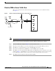
Configuring the Content Switching Module Figure 8 Configuring VLANs Catalyst 6500 Client-side VLAN IP address Content Services Gateway Server-side VLAN * NAS HSRP Content provider ** PDA handset 55703 Gateway See Figure 8 for the following notes: Note *Any router configured as a client-side gateway or a next hop router for servers more than one hop away must have ICMP redirects disabled. The CSM does not perform a Layer 3 lookup to forward traffic; the CSM cannot act upon ICMP redirects.
Configuring the Content Switching Module Configuring Client-Side VLANs To configure client-side VLANs, perform this task: Caution You cannot use VLAN 1 as a client-side or server-side VLAN for the CSM. Command Purpose Step 1 Router(config)# ip slb vlan vlanid client Configure the client-side VLANs and enter the client VLAN mode1. Step 2 Router(config-slb-vlan-client)# ip ip-address netmask Configure an IP address to the CSM used by probes and ARP requests on this particular VLAN2.
Configuring the Content Switching Module This example shows how to configure the CSM for server-side VLANs: Router(config)# ip slb vlan 150 Router(config-slb-vlan-server)# Router(config-slb-vlan-server)# Router(config-slb-vlan-server)# Router(config-slb-vlan-server)# server ip addr 123.46.50.6 255.255.255.0 route 123.50.0.0 255.255.0.0 gateway 123.44.50.1 alias 123.60.7.6 255.255.255.0 exit Configuring Server Farms A server farm or server pool is a collection of servers that contain the same content.
Configuring the Content Switching Module This example shows how to configure a server farm, named p1_nat, using the least-connections (leastconns) algorithm. The least-connections algorithm specifies which real server handles the next new connection for this server farm. Router(config)# ip slb serverfarm pl_nat Router(config-slb-sfarm)# predictor leastconns Configuring Real Servers Real servers are physical devices assigned to a server farm. Real servers provide the services that are load balanced.
Configuring the Content Switching Module This example shows how to create real servers: Router(config)# ip slb serverfarm serverfarm Router(config-slb-sfarm)# real 10.8.0.7 Router(config-slb-real)# inservice Router(config-slb-sfarm)# real 10.8.0.8 Router(config-slb-real)# inservice Router(config-slb-sfarm)# real 10.8.0.9 Router(config-slb-real)# inservice Router(config-slb-sfarm)# real 10.8.0.
Configuring the Content Switching Module Command Purpose Step 5 Router(config-slb-policy)# client-group value | std-access-list-name Configure a client filter associated with a policy. Only standard IP access lists are used to define a client filter. Refer to the Catalyst 6000 Family Software Configuration Guide for information about configuring access lists. Step 6 Router(config-slb-policy)# serverfarm serverfarm-name Configure the server farm serving a particular load-balancing policy.
Configuring the Content Switching Module Table 3 UNIX File Name Specifications (continued) Convention Description A leading ^ in a range Do not match any in the range. All other characters represent themselves. .\a Alert (ascii 7). .\b Backspace (ascii 8). .\f Form-feed (ascii 12). .\n Newline (ascii 10). .\r Carriage return (ascii 13). .\t Tab (ascii 9). .\v Vertical tab (ascii 11). .\0 Null (ascii 0). .\\ Backslash. .
Configuring the Content Switching Module Router(config-slb-sfarm)# real 10.8.0.27 Router(config-slb-real)# inservice Router(config-slb-real)# exit Router(config-slb-sfarm)# exit Router(config)# ip slb policy policy_url_2 Router(config-slb-policy)# serverfarm pl_url_url_2 Router(config-slb-policy)# url-map url_2 Router(config-slb-policy)# exit Router(config)# ip slb vserver vs_url_url Router(config-slb-vserver)# virtual 10.8.0.
Configuring the Content Switching Module Configuring Virtual Servers Virtual servers represent groups of real servers and are associated with real server farms through policies. Configuring virtual servers requires setting the attributes of the virtual server specifying the default server farm (default policy) and eventually associating other server farms through a list of policies. Note A single virtual server can be configured to operate at either Level 4 or Level 7.
Configuring the Content Switching Module This example shows how to configure a virtual server named barnett, associate it with the server farm named bosco, and configure a sticky connection with a duration of 50 seconds to sticky group 12: Router(config)# ip slb vserver barnett Router(config-slb-vserver)# virtual 12.3.23.
Configuring the Content Switching Module To configure DFP, perform this task: Command Purpose Step 1 Router(config)# ip slb dfp [password password] Configure DFP manager, supply an optional password, and enter the DFP agent submode1, 2.
Configuring the Content Switching Module Command Purpose Step 5 Router(config-redirect-v)# idle duration Set the CSM connection idle timer for the redirect virtual server2. Step 6 Router(config-redirect-v)# client ip-address network-mask [exclude] Configure the combination of the ip-address and network-mask used to restrict which clients are allowed to access the redirect virtual server2. Step 7 Router(config-redirect-v)# inservice Enable the redirect virtual server and begin advertisements2.
Writing and Restoring Configurations Command Purpose Step 3 Router(config-slb-serverfarm)# nat clientpool-name Associate the configured NAT pool with the server farm. Step 4 Router# show ip slb natpool [name pool-name] [detail] Display the NAT configuration. 1. Enter the exit command to leave a mode or submode. Enter the end command to return to the menu’s top level. 2. The no form of this command restores the defaults.
Configuration Examples Configuration Examples Caution All examples assume that the ip slb mode csm command has been entered as described in “Configuring the Content Switching Module” section on page 19.
Configuration Examples Note You configure single subnet (bridge) mode by assigning the same IP address to the CSM client and server VLANs. To configure Content Switching for the single subnet (bridge) mode, perform this task: Command Purpose Step 1 Router(config)# vlan database Enter the VLAN mode1. Step 2 Router(vlan)# vlan 2 Configure a client-side VLAN2. Step 3 Router(vlan)# vlan 3 Configure a server-side VLAN. Step 4 Router(vlan)# exit Exit to have the configuration take effect.
Configuration Examples Secure (Router) Mode Configuration In secure (router) mode, the client- and server-side VLANs are on different subnets. Figure 10 shows how the secure (router) mode configuration is set up. Figure 10 Note Secure (Router) Mode Configuration The addresses in Figure 10 refer to the steps in the following task table. To configure Content Switching in secure (router) mode, perform this task: Command Purpose Step 1 Router(config)# vlan database Enter the VLAN mode1.
Configuration Examples Step 9 Command Purpose Router(config)# ip slb vlan 3 server Create the server-side VLAN 3 and enter the SLB VLAN mode. Step 10 Router(config-slb-vlan-server)# ip addr Assign the CSM IP address on VLAN 3. 192.158.39.10 255.255.255.0 Step 11 Router(config-slb-vlan-server)# exit Exit the submode. Step 12 Router(config)# ip slb vserver VIP1 Create a virtual server and enter the SLB vserver mode. Step 13 Router(config-slb-vserver)# virtual Create a virtual IP address. 192.
Configuration Examples QoS Configuration Topology Switch-1 CSG (Active) Switch-2 CSG (Standby) Heartbeat message port gl/1 port gl/1 (sending) (receiving) 63035 Figure 11 Without this configuration, 802.1Q priority information is not preserved in packets traversing through to the switch. Heartbeat messages sent from the primary to the secondary CSM must contain this priority information so that they will be transmitted without delay.
Configuration Examples In the fault-tolerant configuration, the following rules apply: Configuration Parameter On Both Content Switching Modules Same VLAN name X VLAN address 1 Different X Gateway address X Virtual server name X Virtual IP address X Alias IP addresses X Redundancy group name X Redundancy VLAN ID X 1. Server default gateways must point to the alias IP address.
Configuration Examples Figure 12 Fault-Tolerant Configuration Content Services Gateway Client-side Server-side Virtual server 1 Alias IP address A (default gateway) 192.158.38.20 Gateway 192.158.38.20 Server A Router A 192.158.38.10 HSRP VLAN 2 NAS router 192.158.39.10 VLAN 9 Router B IP address 192.158.39.30 192.158.38.40 Gateway 192.158.38.20 Server B Alias IP address (default gateway) 192.158.38.20 B Alias IP address (default gateway) 192.158.39.
Configuration Examples Command Purpose Step 5 Router(config-slb-vserver)# virtual 192.158.38.30 tcp www Create a virtual IP address. Step 6 Router(config)# ip slb vlan 3 server Create the server-side VLAN 3 and enter the SLB VLAN mode. Step 7 Router(config-slb-vserver)# ip addr 192.158.39.10 255.255.255.0 Assign the CSM IP address on VLAN 2. Step 8 Router(config-slb-vserver)# alias ip addr 192.158.39.20 255.255.255.0 Assign the default route for VLAN 2.
Configuration Examples Configuring HSRP This section provides an overview of a Hot Standby Router Protocol (HSRP) configuration (see Figure 13) and describes how to configure the CSMs with HSRP and CSM failover on the Catalyst 6000 family switches. HSRP Configuration Overview The figure shows two Catalyst 6000 switches, Switch 1 and Switch 2, are configured to route from a client-side network (10.100/16) to an internal CSM client network (10.6/16, VLAN 136) through an HSRP gateway (10.100.0.1).
Configuration Examples Figure 13 HSRP Configuration Switch 1 Name: "FT1" HSRP Active 10.6.0.2 CSG#1 FT Active 10.100.0.2 Client Network EtherChannel ID = 100 (Trunk) VLAN 136 Allowed 10.5.0.2 Internal CSG Client Network 10.6/16 10.100/16 VLAN 71 FT Network Server Network 10.5.0.3 10.5/16 10.100.0.3 Switch 2 Name: "FT2" HSRP Standby HSRP ID 2 (Gateway = 10.100.0.1) VLAN 136, Client Network HSRP ID 1 (Gateway = 10.6.0.1) With tracking ON CSG#2 FT Standby 56000 10.6.0.
Configuration Examples Configuring CSM VLANs This section describes how to create a fault-tolerant HSRP secure-mode configuration. To create a nonsecure-mode configuration, enter the commands described with these exceptions: Step 1 • Assign the same IP address to both the server-side and the client-side VLANs. • Do not use the alias command to assign a default gateway for the server-side VLAN. Configure VLANs on HSRP FT1 as follows: ip slb mode csm ip slb vlan 136 client ip address 10.6.0.245 255.
Configuring Probes for Health Monitoring Step 3 Configure EtherChannel on both switches as follows: interface Port-channel100 switchport switchport trunk encapsulation dot1q switchport trunk allowed vlan 136 Note By default, all VLAN's are allowed on the port channel.
Configuring Probes for Health Monitoring After you configure a probe, associate single or multiple probes with a server farm. All servers in the server farm receive probes of the probe types that are associated with that pool. Note If you associate a probe of a particular type with a server farm containing real servers that are not running the corresponding service, the real servers send error messages when they receive a probe of that type.
Configuring Probes for Health Monitoring Commands Available to all Probe Configurations These commands are common to all probe types: Command Purpose Router(config-slb-probe)# interval seconds Set the interval between probes in seconds (from the end of the previous probe to the beginning of the next probe)1. Range = 5–65535 Default = 120 seconds Router(config-slb-probe)# retries retry-count Set the number of failed probes that are allowed before marking the server as failed1.
Configuring Probes for Health Monitoring Step 3 Command Purpose Router(config-slb-probe-http)# expect status min-number [max-number] Configure a status code to expect from the HTTP probe. You can configure multiple status ranges by entering one expect command at a time1. min-number—If you do not specify a max-number, this number is taken as a single status code. If you specify a max-number, this number is taken as the minimum status code of a range. max-number—The maximum status code in a range.
Configuring Probes for Health Monitoring TCP Probe A TCP probe establishes and removes connections. The ip slb probe tcp command enters the TCP probe configuration mode. All the common ip slb probe commands are supported. Command Purpose Step 1 Router(config)# ip slb probe probe-name tcp Configure a TCP probe and enter the TCP probe submode1.
Configuring Route Health Injection To specify the domain name resolve request, perform this task: Command Purpose Step 1 Router(config)# ip slb probe probe-name dns Configure an DNS probe and enter the tcp probe submode1. Step 2 Router(config-slb-probe-dns)# [expect | failed | interval | retries | receive] Configure times to wait between probes to make a DNS connection, to receive a reply from the server, and to limit the number of retries before considering the real server as failed. 1.
Configuring Route Health Injection Note On power-up with RHI enabled, the CSM sends a message to the MSFC as each VIP address becomes available. The MSFC periodically propagates the VIP address availability information that RHI provides. Note RHI is normally restricted to intranets because, for security reasons, most routers do not propagate host-route information to the Internet.
Configuring Route Health Injection Understanding How the CSM Determines VIP Availability For the CSM to determine if a VIP is available, you must configure a probe (HTTP, ICMP, Telnet, TCP, FTP, SMTP, or DNS) and associate it with a server farm.
Regulatory Standards Compliance Regulatory Standards Compliance Catalyst 6000 family switching modules, when installed in a system, comply with the standards listed in Table 4. Table 4 Regulatory Standards Compliance Agency Approvals Description Compliance CE1 Marking Safety UL2 1950, CSA3-C22.2 No.
Translated Safety Warnings Attention Avant d'installer le système, de l'utiliser ou d'assurer son entretien, veuillez lire le Guide de sécurité et de préparation du site. Celui-ci présente des informations importantes relatives à la sécurité, dont vous devriez prendre connaissance. Warnung Warnhinweis Bevor Sie das System installieren, in Betrieb setzen oder warten, lesen Sie die Anleitung zur Standortvorbereitung und Sicherheitshinweise.
Translated Safety Warnings Attention Lors de cette procédure, toujours porter des bracelets antistatiques pour éviter que des décharges électriques n’endommagent la carte. Pour éviter l’électrocution, ne pas toucher le fond de panier directement avec la main ni avec un outil métallique. Warnung Zur Vermeidung einer Beschädigung der Karte durch elektrostatische Entladung während dieses Verfahrens ein Erdungsband am Handgelenk tragen.
Translated Safety Warnings Varoitus Tyhjillä kansilaatoilla (peitelevyillä) on kolme tehtävää: ne suojaavat vaarallisilta asennuspohjan sisäisiltä jännitteiltä ja virroilta; suojaavat sähkömagneettiselta häiriöltä (EMI), joka voi haitata muiden laitteiden toimintaa; ja ohjaavat jäähdytysilmavirran asennuspohjan läpi. Laitetta ei saa käyttää, jos kaikki kortit ja peitelevyt eivät ole paikoillaan.
Related Documentation Qualified Personnel Warning Warning Waarschuwing Varoitus Avertissement Achtung Avvertenza Advarsel Aviso ¡Atención! Varning Only trained and qualified personnel should be allowed to install or replace this equipment. Installatie en reparaties mogen uitsluitend door getraind en bevoegd personeel uitgevoerd worden. Ainoastaan koulutettu ja pätevä henkilökunta saa asentaa tai vaihtaa tämän laitteen.
Obtaining Documentation Obtaining Documentation The following sections provide sources for obtaining documentation from Cisco Systems. World Wide Web You can access the most current Cisco documentation on the World Wide Web at the following sites: • http://www.cisco.com • http://www-china.cisco.com • http://www-europe.cisco.com Documentation CD-ROM Cisco documentation and additional literature are available in a CD-ROM package, which ships with your product.
Obtaining Technical Assistance Obtaining Technical Assistance Cisco provides Cisco.com as a starting point for all technical assistance. Customers and partners can obtain documentation, troubleshooting tips, and sample configurations from online tools. For Cisco.com registered users, additional troubleshooting tools are available from the TAC website. Cisco.com Cisco.
Obtaining Technical Assistance Contacting TAC by Telephone If you have a priority level 1(P1) or priority level 2 (P2) problem, contact TAC by telephone and immediately open a case. To obtain a directory of toll-free numbers for your country, go to the following website: http://www.cisco.com/warp/public/687/Directory/DirTAC.shtml P1 and P2 level problems are defined as follows: • P1—Your production network is down, causing a critical impact to business operations if service is not restored quickly.
Obtaining Technical Assistance This document is to be used in conjunction with the documents listed in the “Related Documentation” section.