
Bridge/Router Installation Guide


4-28
Cisco CRS-1 Carrier Routing System 4-Slot Line Card Chassis Installation Guide
OL-10971-07
Chapter 4 Installing and Removing SFCs, RPs, MSCs, PLIMs, and Associated Components
How to Install or Remove a Route Processor Card
Required Tools and Equipment
You need the following tools and part to perform this task:
• ESD-preventive wrist strap
• Large Phillips screwdriver
• Route processor card (Cisco product number: CRS-8-RP=)
Steps
To install a route processor card, follow these steps:
Step 1 Go to the front of the chassis. Attach the ESD-preventive wrist strap to your wrist and connect its leash
to one of the ESD connection sockets on the rear side of the chassis or a bare metal surface on the chassis.
Step 2 Remove the route processor card from its antistatic packaging.
Step 3 Use a medium Phillips screwdriver to remove the route processor card from its protective carrier.
Step 4 Visually inspect the connector pins on the card before you insert it into the chassis.
Note Do not attempt to install a card with bent pins, because this may damage the chassis midplane
connectors.
Step 5 Identify the card slot in the card cage where the route processor card should be installed.
a. If there is an impedance carrier in the slot, remove it (see the “Removing an Impedance Carrier”
section on page 4-10.)
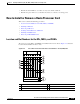
b. If there is an RP card already installed in the slot, remove any cables connected to the front panel of
an existing card in the slot, then remove the card (see the
“Removing an RP Card” section on
page 4-29).
Step 6 Grasp the face plate of the card with one hand and place your other hand under the card to support and
guide it into the correct slot.
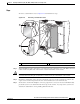
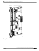
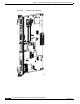
Step 7 Orient the route processor card so that the status display is on top, then position the card for insertion
into the card cage slot. Avoid touching the card circuitry or any connectors.
Note There are alignment grooves on each slot in the card cage. When you install a card in the card
cage, make sure that you align both the top and bottom edges of the card carrier in the slot
grooves.
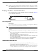
Step 8 Grasp both card ejector levers simultaneously, then push them both outward until they are fully extended
in the open position.
Step 9 Carefully slide the route processor card into the slot until the ejector levers meet the edges of the card
cage, then stop when the ejector lever hooks catch the lip of the card cage. If they do not catch, try
reinserting the route processor card until the ejector lever hooks are fully latched.