
Bridge/Router Installation Guide


4-26
Cisco CRS-1 Carrier Routing System 4-Slot Line Card Chassis Installation Guide
OL-10971-07
Chapter 4 Installing and Removing SFCs, RPs, MSCs, PLIMs, and Associated Components
How to Install or Remove a Route Processor Card
Installing an RP Card
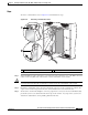
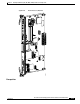
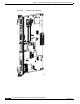
This section describes how to install a route processor (RP) card in the chassis (see Figure 4-18). For
more detailed information on the route processor card, see Cisco CRS-1 Carrier Routing System 4-Slot
Line Card Chassis System Description.
Every Cisco CRS-1 4-slot line card chassis contains two RP cards in dedicated slots on the front (PLIM)
side of the chassis (see
Figure 4-18).
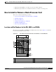
Note For enhanced immunity to external electromagnetic disturbance levels of 10 V per meter and 10 V RMS,
you must use a shielded Ethernet (CAT5 or better STP) cable on the Management Ethernet connection
of the route processor card.
RP Installation Guidelines
Chassis operation may be effected by the installation of a route processor card. A route processor card
is normally installed under one of the following conditions:
• When you are certain that the second RP in the chassis is operational and, if not already the active
RP, ready to assume control (this happens automatically).
• When the chassis is undergoing scheduled maintenance.
• When the Cisco CRS-1 4-slot line card chassis is powered down.
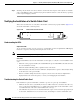
Monitoring the RP Card Start-Up Process
Monitoring the RP card during its start-up process must be done through a console port connection. For
details, see the latest release of the Cisco IOS XR Getting Started Guide on www.cisco.com.
To monitor the RP card during its start-up, follow these steps:
Step 1 Install the console port connection to the front of the RP.
Tip If you want to monitor the start-up process on the RP, you must physically attach the console
port connection and open the console port connection prior to inserting the RP into its designated
slot.
Step 2 Insert the RP into its designated slot as described in this section.
Step 3 At the console, verify the status of the RP.
4 MSC slot 3 10 RP slot (RP1)
5 PLIM slot 0 11 Air intake
6 PLIM slot 1 12 AC or DC power shelf